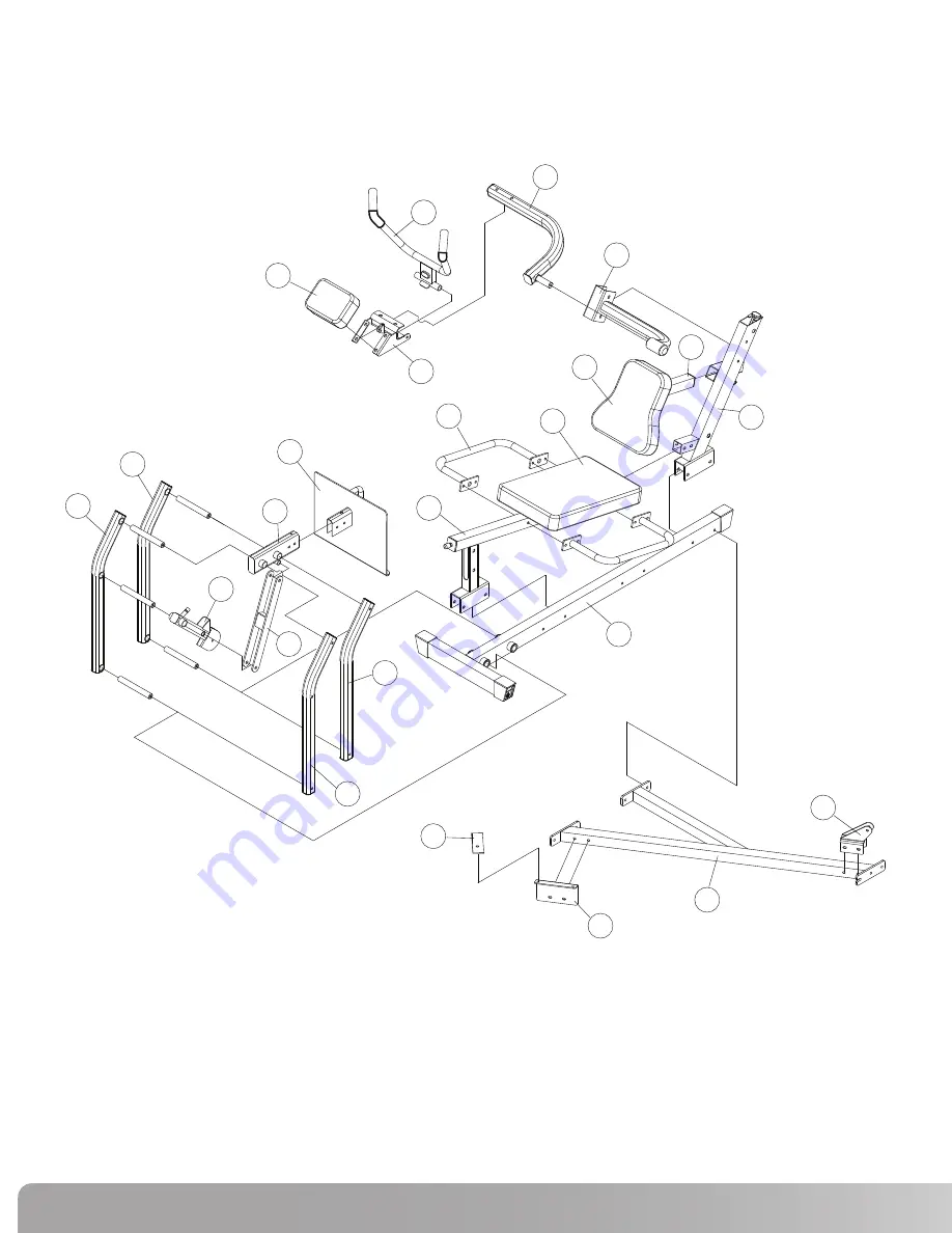
ExPLOdEd VIEW
• Compare the Bill of Materials to the box contents to insure that all parts are present before installation begins.
2
7
12
15
14
6
5
1
10
13
11
8
9
22
24
21
3
4
23
16
20
18
17
19
5 764
Page 1: ...tff NAUT LUS NS75X Assembly Manual h Be Strang Art 200 3418...
Page 2: ...ONTENTS Before You Assemble 3 Product Specifications 4 Product Features 4 Parts List Box Contents 5 Exploded View 6 Hardware and Tool List 7 Assembly Guide 8 Warranty Information 15 Important Contact...
Page 3: ...ssembly instructions for that step prior to starting assembly for the step 2 When tightening a locknut on a bolt use a combination wrench to grip the locknut and ensure that it is fastened securely 3...
Page 4: ...ons in the manual are given with the orientation of sitting on the machine ready to exercise User Weight Capacity 300lbs 136 1Kg Dimensions 56 w x 76 l x 46 h 142 cm x 193 cm x 117 cm Shipping Weight...
Page 5: ...port Assembly 1 17 Seat Back Adjuster 1 18 Ab Crunch Support Arm 1 19 Ab Crunch Arm 1 20 Ab Crunch Handle 1 21 Ab Crunch Pad Support 1 22 Ab Crunch Pad 1 23 Leg Press Seat Pad 1 24 Leg Press Back Pad...
Page 6: ...Exploded view Compare the Bill of Materials to the box contents to insure that all parts are present before installation begins 2 7 12 15 14 6 5 1 10 13 11 8 9 22 24 21 3 4 23 16 20 18 17 19 5 7 6 4...
Page 7: ...Nautilus NS75X Hardware and tools NS 75...
Page 8: ...75X Leg Press attachment can be assembled in a right or left configuration for use on the NS300X NS200X NS600X and NS700X You may also mount the Ab Crunch arm on either side to most efficiently use sp...
Page 9: ...he rear bolt on the gyms foot plate B If using a NS200X NS300X or NS600X attach the Vertical Pulley Bracket 5 to the connecting Tube Assembly 2 using the hardware shown above C Tighten all hardware se...
Page 10: ...the Main Base Assembly 1 and position next to the Connecting Tube Assembly 2 Secure parts with hardware shown above but do not tighten B Slide the Seat Tube Assembly 3 over the Seat Back Support Asse...
Page 11: ...e Leg Press Rear Link Right 13 using the hardware shown above B Slide the shafts into position on the Main Base Assembly C Slide the Leg Press Top Link 8 and the Leg Press Power Arm 14 into position a...
Page 12: ...re shown above B Attach the Ab Crunch Support Arm 18 with preinstalled Ab Crunch Arm 19 to the Seat Back Support Assembly using the hardware shown above This can be done to the right or left C Cover t...
Page 13: ...h the Ab Crunch Pad 22 to the Ab Crunch Pad Support using the hardware shown above B Attach the Seat Back Pad 24 to the Seat Back Adjuster 17 using the hardware shown above Slide the Seat Back Adjuste...
Page 14: ...Tube Assembly out the front C Run the cable over the 3 1 2 Pulleys and attach them to the Seat Tube Assembly using the hardware shown D Attach a 4 1 2 Pulley to the Leg Press Power Arm using the hardw...