Be Strong.
™
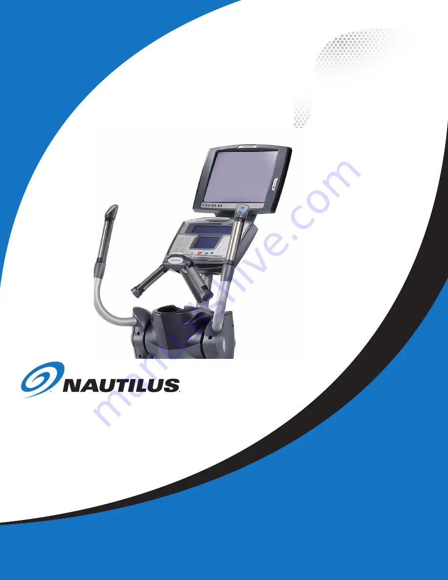
Model:NV915
P/N: 001-1959 Rev C (08/13/2007)
Installation Manual
M-Series LCD Monitor Bracket
Page 1: ...Be Strong Model NV915 P N 001 1959 Rev C 08 13 2007 Installation Manual M Series LCD Monitor Bracket ...
Page 2: ... Table of Contents FCC Information 3 Safety Precautions 4 Specifications Components Tools Needed 5 Installation Procedure 6 Quick Reference Guide 17 Important Contact Information 18 ...
Page 3: ... installation If this equipment does cause unacceptable interference to radio and television reception which can be determined by turning the equipment off and on the user is encouraged to try to correct the interference by one or more of the following measures Reorient or relocate the receiving antenna Increase the separation between the equipment and receiver Connect the equipment to an outlet o...
Page 4: ...sources Do not place heavy articles on or step on the LCD Monitor The product should be installed in a clean and dry place If you detect any smoke unusual noise or smell disconnect the electric power and contact service Avoid contact with liquids or beverages Do not use or place any combustible or flammable substances close to the LCD Monitor Do not place the power cord close to any heating device...
Page 5: ...UK Ireland Part 001 2019 Australia Owners Manual CD Part 001 7167 Power Supply Part 000 8010 Part 002 3787 Digital Hardware Kit Part 001 1938 WireTies International Coax Adapter Part 001 1995 Tools Needed 3 16 Allen wrench 6mm Allen Wrench Wire Cutter Phillips Head Screwdriver Product Specifications Contents Tools Needed M Series Bracket Gross Weight 8 0 lbs 3 63 kg Net Weight 4 75 lb 2 15 kg Prod...
Page 6: ...our screws that secure the Console Tools Needed Wire cutter or similar 2 1 Locate the LCD wires inside the mast Figure A 2 2 Remove the wire tie Figure B 2 3 Extend approximately 12 of the LCD wires Figure C Step 2 Locate the LCD wires and remove the wire tie Phillips Head Screw Figure A Figure B Figure C LCD Wires WireTie Extend 12 of Wire ...
Page 7: ...p 4 Remove the Back Cover of the LCD Bracket 3 1 Place the Spacer Figure A between the Console and Mast as shown Figure B 3 2 Allow the LCD wires to extend through the gap between the Spacer and the Console and over top of the Mast Figure C 3 3 Leave the Console in place on the Mast but do not install the hardware at this time Figure A Spacer Spacer Console Mast Spacer Console Mast LCD Wires Figur...
Page 8: ...etween the metal plate and the plastic cover as shown Figure A 5 2 Align the Bracket with the Console mounting holes on the Mast Figure B 5 3 Replace the original Console hardware with the four 1 4 x 1 Phillips Screws provided 5 4 Completely tighten the hardware Figure C LCD Wires Plastic Cover Metal Plate Pass Wires through Bracket LCD wires Mast 1 4 x1 Phillips Screw Figure A Figure B Figure C ...
Page 9: ...to install the LCD Monitor NOTE To keep the LCD Wires in place it is helpful to pass them through the Bracket as shown Tools Needed Phillips Head Screwdriver 6 1 Use a Phillips Head Screwdriver to remove the Back Cover of the LCD monitor Figure A Figure A Back Cover ...
Page 10: ...e upright prongs discussed in Step 6 Detail A 7 2 Install the M10 Allen Bolts and Lock Washers From Hardware Kit 7 3 Position the LCD Monitor Figure B C Note The Monitor has a 30º range of viewing angles Position at your dis cretion Figure B C 7 4 Completely tighten the M10 Allen Bolts Figure A Detail A LCD Monitor Bracket MetalTab Prong 30º Range 30º Range Figure B Figure C ...
Page 11: ...cidental disconnection Power Antenna Power For alternative configurations please refer to the LCD Monitor owners manual These connections are not used in this configuration Antenna NOTE International version will require supplied Coaxial Connection Adapter International Coaxial Adapters WireTie NOTE If you are using the optional Wired Remote attach the end labeled LCDTV at this time Refer to Wired...
Page 12: ... 9 1 Use the M4 Screws and Washers from the Hardware Kit to replace the Back Cover of the Bracket Figure A and the LCD Monitor Figure B NOTE Use the two longer screws on the raised portion of the LCD Monitor Back cover Detail A Figure A Bracket Back Cover Use longer screws here Figure B Detail A ...
Page 13: ...ctor Power For Unit TV Power Connector Attention After steps 1 9 of the M Series installation manual use this page to make connections to EV916 E916 Commercial Bikes and the future redesigns of the stepper If you are installing the monitor on an elliptical unit proceed to Step 10 If you are installing the monitor on any product other than an elliptical installation is complete after making the con...
Page 14: ...ools Needed Two WireTies 11 1 Connect the Power Wire to the power connection on top of the Frame Figure A 11 2 Secure the Power Brick to the Mast using two WireTies as shown Figure B Power Connection Power Wire WireTie Power Brick Mast Figure A Figure B Attention The following steps apply to pre wired Commercial Ellipticals only For non pre wired instructions refer to the appropriate LCD wiring ma...
Page 15: ...llips Head Screwdriver 13 1 Replace the Right Shroud removed in Step 10 Step 14 Connect LCD Wires 14 1 Make appropriate Coax and Power connections where LCD Wires exit the unit NOTE International versions will require supplied Coaxial Connection adapter Figure C International Coaxial Adapters Note You may have to adjust the leveler feet to allow enough clearance for the LCDWires Adjust the feet en...
Page 16: ...Installation Procedure Installation is complete For specific instructions on setup and use of the LCD Monitor please refer to the LCD Monitor Users Manual 16 ...
Page 17: ...r Volume UP Video Input Source Video S Video Antenna Volume Down Mute Channel Down 7 8 7 Channel Up 8 Numeric Channel Keys Headphone Jack Infrared remote Receiver Power Light For specific instructions on setup and use of the LCD Monitor please refer to the LCD Monitor Users Manual ...
Page 18: ...ce listed below INTERNATIONAL OFFICES For technical assistance and a list of distributors in your area please call or fax one of the following numbers INTERNATIONAL CUSTOMER SERVICE Nautilus International S A Rue Jean Prouvé 6 1762 Givisiez Switzerland Tel 41 26 460 77 77 Fax 41 26 460 77 70 Email technics nautilus com INTERNATIONAL OFFICES SWITZERLAND OFFICE Nautilus Switzerland S A Tel 41 26 460...
Page 19: ... rights reserved Nautilus the Nautilus logo and Be Strong are either registered trademarks or trademarks of Nautilus Inc All other marks are either registered trademarks or trademarks of their respective companies Nautilus Inc World Headquarters 16400 SE Nautilus Drive Vancouver Washington USA 98683 1 800 628 8458 www Nautilus com ...