Nautilus Be Strong. NV915, Assembly Manual
Introducing the Nautilus Be Strong. NV915, a versatile home gym equipment designed to help you achieve your fitness goals. Ensure a seamless setup with our detailed Installation Manual, available for free download from our website. Get the most out of your Nautilus Be Strong and start your fitness journey today!
Share
Download


Reviews:
No comments
Related manuals for Be Strong. NV915
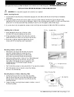
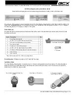
M Series
Brand: GCX Pages: 3
M Series
Brand: GCX Pages: 3
E220
Brand: Barkan Pages: 34
E410
Brand: Barkan Pages: 34
E321
Brand: NEC Pages: 7
TY-WK5P1SW
Brand: Panasonic Pages: 11
S40
Brand: Barkan Pages: 8
hp2xf-o
Brand: 3idee Pages: 7
PT2
Brand: Rawinternational Pages: 2
43
Brand: Barkan Pages: 8
E210
Brand: Barkan Pages: 34
Levante
Brand: MAIOR Pages: 19
B SERIES
Brand: Eaton Pages: 4
CB1
Brand: Eclipse Pages: 12
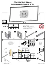
EGMF1
Brand: Echogear Pages: 2
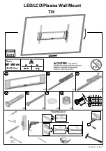
PF400
Brand: Kanto Pages: 16
RWB
Brand: jbc Pages: 12
PS400
Brand: Kanto Pages: 16


