background image


Installation Manual                                                                                                                      Chapter4. System Installation   


©  

Nautilus Hyosung, Inc. 

All Rights Reserved

.


4-5


Inserting the Collar Wing 


 Inserting the Collar Wing 

1. Unlocking the collar locking bracket 

  Turn off the power 

  Open the side door   


  Unscrew the captive screw on the collar stop bracket inside the upper body. 


2. Lift the collar wing so that the pin at the back of the bezel fits into the hole. 
3. Push the collar wing in and then push it downward completely. 


Summary of Contents for MX7600DR

Page 1: ...Installation Manual MX7600DR System V01 01 00 2014 01 2011 Nautilus Hyosung Inc All Rights Reserved...

Page 2: ...stem No Version Date Description of Change Chapter 1 V01 00 00 2011 10 New Publication All 2 V01 01 00 2014 02 Update to standard format and replace EDU P to CCIM All Nautilus Hyosung Inc All Rights R...

Page 3: ...ature humidity 3 2 Tools required for installation 3 2 Packing Dimensions 3 3 ATM Dimensions 3 3 Dimension for tilt angle 3 6 Fascia Item Locations for Voice Guidance 3 8 Recommended Installation and...

Page 4: ...staffs of Nautilus Hyosung Inc see the E mail addresses and telephone numbers provided separately What is in This Manual This manual is designed to provide the installation guide for the MX7600DR and...

Page 5: ...er Servicing and maintenance refer to the supervisor operator and technician s tasks performed to keep the ATM operational Screen refers to the text appearing on the customer display Abbreviations of...

Page 6: ...nal Transfer Systems 30 JPR Journal Printer 31 LCD Liquid Crystal Display 32 MCU Magnetic Card Unit 33 OPL Operation Panel for Customers to Operate 34 OSD board On Screen Display Board 35 P S Power Su...

Page 7: ...ifications in construction of this device which are not expressly approved by the party responsible for compliance could void the user s authority to operate the equipment Note This equipment has been...

Page 8: ...sembly may cause fire or electrical shock Collapse Precautions Do not place the equipment where the floor cannot sustain the weight of the equipment or on slanted or unstable surface Equipment may fal...

Page 9: ...n changement ou des modifications dans la construction de ce dispositif qui ne sont pas express ment approuv s par la partie responsable de la conformit pourraient annuler l autorit de l utilisateur d...

Page 10: ...cendie ou un choc lectrique Tomber Ne pas placer l quipement dont le sol ne peut pas supporter le poids de l quipement ou sur une surface inclin e ou instable L quipement peut tomber et provoquer des...

Page 11: ...related documents are listed as follows If needed please contact staffs of our technical support team and maintenance team Operator Manual Service Manual Error Code Manual For the contact of maintena...

Page 12: ...escription of the following Information for installation Environmental Specification Power Specification The benefits that the new concept MX7600DR provides are as follows 1 Removes inconvenience whic...

Page 13: ...ter3 Installation Information Nautilus Hyosung Inc All Rights Reserved 3 1 System Identification Label The System Label below shows the layout of the product identification label which is fixed inside...

Page 14: ...loor must allow easy wheelchair access from the front or the side Space required for servicing the machine should be considered before installation Environmental Specification temperature humidity Env...

Page 15: ...s The design of packing used on below picture is structured for shipping of MX 7600DR by load or air sea freight Note Approximate weight of a boxed MX7600DR ATM is 700 0Kg 1543 23Ib Actual weight will...

Page 16: ...Installation Manual Chapter3 Installation Information Nautilus Hyosung Inc All Rights Reserved 3 4...

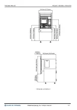
Page 17: ...Installation Manual Chapter3 Installation Information Nautilus Hyosung Inc All Rights Reserved 3 5 Dimension of Outline...

Page 18: ...al Chapter3 Installation Information Nautilus Hyosung Inc All Rights Reserved 3 6 Dimension for tilt angle Dimension for tilt angle The following diagrams show the dimensions for tilt angle of MX 7600...

Page 19: ...Installation Manual Chapter3 Installation Information Nautilus Hyosung Inc All Rights Reserved 3 7 1Step 22 2Step 35...

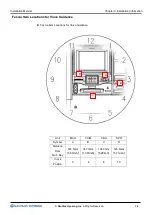
Page 20: ...c All Rights Reserved 3 8 Fascia Item Locations for Voice Guidance Fascia Item Locations for Voice Guidance Unit MCU CCIM CDU SPR Symbol A B C D Distance 167 5mm 6 59inch 347 3mm 13 67inch 134 0mm 5 2...

Page 21: ...nce Recommended Installation and Service Clearance Following diagram is describing the recommended areas required for installing and servicing the MX 7600DR Hyousng recommends it is more convenient fo...

Page 22: ...ance Following diagram is describing the Following diagram is describing the minimum areas required for installing and servicing the MX 7600DR Plane cross Sectional View MINIMUM To service Cash dispen...

Page 23: ...Installation Manual Chapter3 Installation Information Nautilus Hyosung Inc All Rights Reserved 3 11 Wall Cut Plan Wall Cut Plan General View Wall Construction Plan A...

Page 24: ...mum thickness of wall that enables you to install TTW should not be exceeded 190 0mm 7 48 inch 2 The installation of a TTW is based on the floor from customer s foot of outside building 3 The minimum...

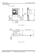
Page 25: ...Installation Manual Chapter3 Installation Information Nautilus Hyosung Inc All Rights Reserved 3 13 Sensor Installation Sensor Installation Sensor of Installation Dimension of Sensor...

Page 26: ...Installation Manual Chapter3 Installation Information Nautilus Hyosung Inc All Rights Reserved 3 14 Sensing Range...

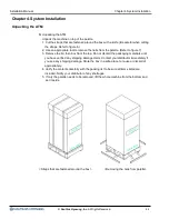
Page 27: ...r to figure 7 3 Remove the lid then box from the top Do not discard the packaging materials until you have verified any shipping damage claim Contact your distributor immediately if you see any shippi...

Page 28: ...ith a spanner 3 Lifting equipment using a lifting device 4 Moving this ATM machine to the installation site PRECAUTION MX7600DR ATM machine is very heavy equipment and can cause injuries if not handle...

Page 29: ...Installation Manual Chapter4 System Installation Nautilus Hyosung Inc All Rights Reserved 4 3 System Positing System Positing Position equipment through the opening in the wall and adjust its position...

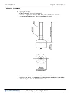
Page 30: ...ight Adjust the height by turning the adjuster nut 1 Lower the height as much as possible while making it as level as possible 2 This ATM machine can fall if you turn the adjuster too much 3 Adjust th...

Page 31: ...serting the Collar Wing 1 Unlocking the collar locking bracket Turn off the power Open the side door Unscrew the captive screw on the collar stop bracket inside the upper body 2 Lift the collar wing s...

Page 32: ...mly in place Close the thumb screw not to be open it 5 Silicone conclusion Sealing the space between the wall and the collar with silicon is recommending Otherwise it s not effecting to system functio...

Page 33: ...how the location of leading in hole for AC Cord and LAN Cable of MX 7600DR Power Requirements Power Requirements Power Requirements For MX 7600DR with CCIM Operating 319W during dispensing Stand by 22...

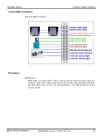
Page 34: ...erface Terminal Block Interface Precaution Precaution MX 7600DR has system battery backup units as optional itself to grantee customer s transaction safety when losing power status This function will...

Page 35: ...his circuit cannot be shared with any other equipment Make sure that the outlet of power at installation site should be grounded by using of meter It is ok that the voltage measurement between mutual...

Page 36: ...Installation Manual Index Nautilus Hyosung Inc All Rights Reserved Index 1 Index...

Page 37: ...Installation Manual Memo Nautilus Hyosung Inc All Rights Reserved Memo 1 Memo...

Reviews: