VS300 Pre-installation Manual
Planning for control and monitoring
Page 8-8
Issue 2.0 2010-12-01
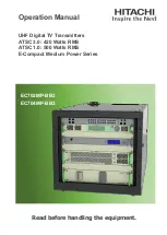
RF monitor sample
A true RF sample of the RF output voltage waveform is available for external monitoring on the
RF
MONITOR
BNC connector (J2) on the rear panel of the transmitter.
Figure 8.3
shows the frequency
response of the RF monitor sample’s coupler. The coupler yields approximately -39dB (± 1.5 dB),
relative to the carrier level, at the FM broadcast carrier frequency (88 - 108 MHz). Note that there is a
“boost” in the coupler response at higher order (harmonic) frequencies. This boost can be up to +15
to +20 dB relative to the carrier frequency. Subtract the boost value - determined from
Figure 8.3
-
from any harmonic measurements made from this sample port. NOTE: there is a 1 to 2 dB tolerance
on the boost values.
Figure 8.3: RF Monitor Sample Frequency Response
150
300
450
600
750
900
1050
1200
1350
1500
Freq (MHz)
Summary of Contents for VS300
Page 2: ......
Page 4: ......
Page 8: ...VS300 Pre installation Manual Page viii Issue 2 0 2010 12 01...
Page 10: ...VS300 Pre installation Manual Page x Issue 2 0 2010 12 01...
Page 24: ...VS300 Pre installation Manual Pre installation tasks Page 2 4 Issue 2 0 2010 12 01...
Page 32: ...VS300 Pre installation Manual Electrical requirements Page 5 4 Issue 2 0 2010 12 01...
Page 34: ...VS300 Pre installation Manual RF output requirements Page 6 2 Issue 2 0 2010 12 01...
Page 52: ...VS300 Pre installation Manual Parts and tools Page 9 4 Issue 2 0 2010 12 01...
Page 58: ...VS300 Pre installation Manual Pre installation assistance Page 10 6 Issue 2 0 2010 12 01...
Page 61: ......