background image

4

Temperature Sensor and Switch Configuration

To enable you to use thermocouples with VXI-SC submodules, the
VXI-TB-1303 terminal block has a thermistor temperature sensor for
cold-junction compensation.

You can connect the temperature sensor to a VXI-SC submodule in either
of two ways:

• 

Multiplexed Temperature Sensor (MTEMP) mode—Set the
VXI-TB-1303 terminal block switch S1 to the MTEMP position.
This is the factory-default setting.

• 

Direct Temperature Sensor (DTEMP) mode—Set the VXI-TB-1303
terminal block switch S1 to the DTEMP position. This mode
connects the temperature sensor to a separate DAQ channel via
your VXI-SC submodule. Refer to your VXI-SC submodule
documentation to configure your VXI-SC submodule for DTEMP
mode.

Table 1 shows the terminal block switch settings.

Table 1.

  Switch S1 Settings

Switch S1 Position

Description

MTEMP

DTEMP

MTEMP mode selected; factory-default
setting; preferred mode and parking
position

MTEMP

DTEMP

DTEMP mode selected; connect to a
separate DAQ channel

Note:

On the VXI-SC-1102 submodule, the MTEMP and DTEMP modes are
equivalent.

Summary of Contents for VXI-TB-1303

Page 1: ...e to minimize the temperature gradients across the screw terminals when you measure with thermocouples The terminal block has 80 screw terminals for easy connection Thirty two pairs of screw terminals connect to the 32 differential inputs of the VXI SC submodule Four terminals labeled GND connect to the submodule s chassis ground pins The AIREF AOREF GUARD OUTPUT OUT0 OUT0 OUT1 OUT1 OUT2 OUT2 OUT3...

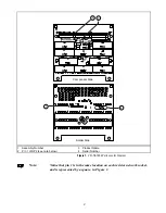
Page 2: ...al board carrier and documentation VXI SC 1102 or other VXI SC submodule s and documentation Long nose pliers Signal Connection and Installation Refer to the VXI TB 1000 Terminal Board Carrier Installation Guide for instructions on connecting your signals and installing the VXI TB 1303 terminal block Warning Do not connect hazardous voltage levels 42 VAC peak or VDC to this product Figure 1 shows ...

Page 3: ...Assembly Number 3 Product Name 2 Pin 1 of RP2 see note below 4 Serial Number Figure 1 VXI TB 1303 Parts Locator Diagram Note Notice that pin 1 is in the same location on each resistor network socket and is represented by a square in Figure 1 ...

Page 4: ...Direct Temperature Sensor DTEMP mode Set the VXI TB 1303 terminal block switch S1 to the DTEMP position This mode connects the temperature sensor to a separate DAQ channel via your VXI SC submodule Refer to your VXI SC submodule documentation to configure your VXI SC submodule for DTEMP mode Table 1 shows the terminal block switch settings Table 1 Switch S1 Settings Switch S1 Position Description ...

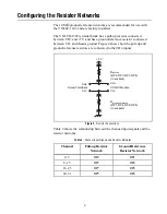
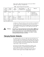
Page 5: ...re 2 shows how the pull up and ground reference resistors are connected to the CH inputs CH CH CH CH VXI SC Module Rpull up RP2 RP3 RP7 RP5 in sockets Rground reference RP1 RP4 RP8 RP6 in sockets Screw Terminals 5 V Figure 2 Resistor Connections Table 2 shows the relationship between the channel input signals and the resistor networks Table 2 Channel Input Signals and Resistor Networks Channel Pul...

Page 6: ...an external ground referenced signal with the 10 Ω Ω Ω Ω ground reference resistor network in place may cause permanent damage to the resistor network and the traces on the VXI TB 1303 printed circuit board National Instruments is NOT liable for any damage or injuries resulting from improper signal connections Changing Resistor Networks Use long nose pliers to remove or replace the resistor networ...

Page 7: ...d reference resistor networks it does not matter whether your signal is ground referenced or floating The channels with open thermocouples will saturate at all sample rates of the submodule Errors Due to Open Thermocouple Detection Circuitry Open thermocouple detection circuitry can cause two types of measurement errors These errors are caused by common mode voltage at the input of the VXI SC subm...

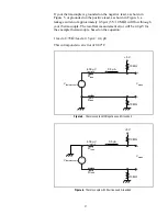
Page 8: ...ent depends on whether your thermocouple is grounded The following calculation uses a 20 ft 24 AWG J type thermocouple as an example This example thermocouple has a resistance of 8 78 Ω per lead based on the equation Rlead 0 439 Ω ft x 20 ft 8 78 Ω per lead If your thermocouple is floating as shown in Figure 4 a leakage current of approximately 0 25 µA 5 V 20 MΩ will flow through both leads of you...

Page 9: ...ermocouple The resultant measurement error will be 4 4 µV for the example thermocouple based on the equation 1 lead x 8 78 Ω lead x 0 5 µA 4 4 µV This corresponds to an error of 0 09 C 4 39 µV 0 5 µA 10 MΩ 10 MΩ 5 V Vthermocouple Vmeas Rlead Rlead Figure 5 Thermocouple with Negative Lead Grounded 4 39 µV 0 5 µA 10 MΩ 10 MΩ 5 V Vthermocouple Vmeas Rlead Rlead Figure 6 Thermocouple with Positive Lea...

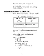
Page 10: ...he combined effects of the temperature sensor accuracy and the temperature difference between the temperature sensor and any screw terminal The temperature sensor accuracy includes tolerances in all component values the effects caused by temperature and loading and self heating To select and read the temperature sensor refer to your LabVIEW LabWindows CVI NI DAQ or other software documentation for...

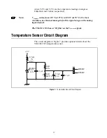
Page 11: ...for this signal range on the analog input channel The VXI SC 1102 has a 2 Hz filter on the VTEMPOUT signal Temperature Sensor Circuit Diagram The circuit diagram in Figure 7 provides optional details about the VXI TB 1303 temperature sensor 4 7 kΩ 1 5 kΩ 0 1 1 2 1 2 2 5 kΩ at 25o C 10 µF 16 V 0 1 µF 0 1 µF to 5 V 2 5 V LM 4040 2 5 V 0 1 MTEMP DTEMP S1 Figure 7 Temperature Sensor Circuit Diagram ...

Page 12: ... Ω or 10 MΩ Maximum field wire gauge 26 14 AWG Maximum working voltage signal common mode Each input should remain within 10 V of chassis ground 1 Includes the combined effects of the temperature sensor accuracy and the temperature difference between the temperature sensor and any screw terminal The temperature sensor accuracy includes tolerances in all component values the effects caused by tempe...

Reviews: