


Chapter 3
Connecting the UMI-7774/7772 to Drives and Other Devices
National Instruments UMI-7774/7772 User Manual
3-28
ni.com
You can wire a Digital Input to a sourcing output device, such as a PNP
sensor, as shown in Figure 3-16. You can use the isolated power (V
iso
) and
isolated common (C
iso
) signals on the control connector to power on the
sensor.
The Digital output circuit sources current source external loads. The
maximum output current when V
iso
is 30 V is 160 mA. The maximum
output current when V
iso
is 24 V is 150 mA. The maximum output current
when V
iso
is 5 V is 60 mA. The output voltage is within 1.2 V of the voltage
provided on the V
iso
power supply. Refer to Figure 3-18 for an illustration
of the Digital output interface circuit.
Refer to the
Voltage Considerations for the UMI-7774/7772
section for
voltage information that applies to the general-purpose digital I/O lines.
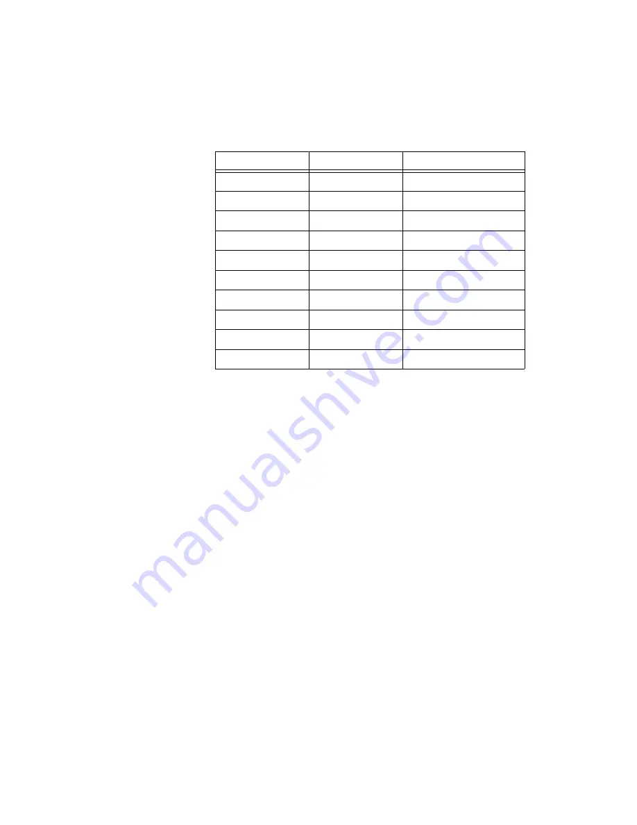
16
Digital Input 5
Yes
17
Digital Input 7
Yes
18
Iso Common
Yes
19
Iso Common
Yes
20
Iso Common
Yes
21
Digital Output 1
Yes
22
Digital Output 3
Yes
23
Digital Output 5
Yes
24
Digital Output 7
Yes
25
Iso Common
Yes
Table 3-9.
Digital I/O Connector Pin Assignment (Continued)
Pin
Signal
Optically Isolated


