©
National Instruments Corporation
29
UMI Accessory User Guide — UMI-Flex4
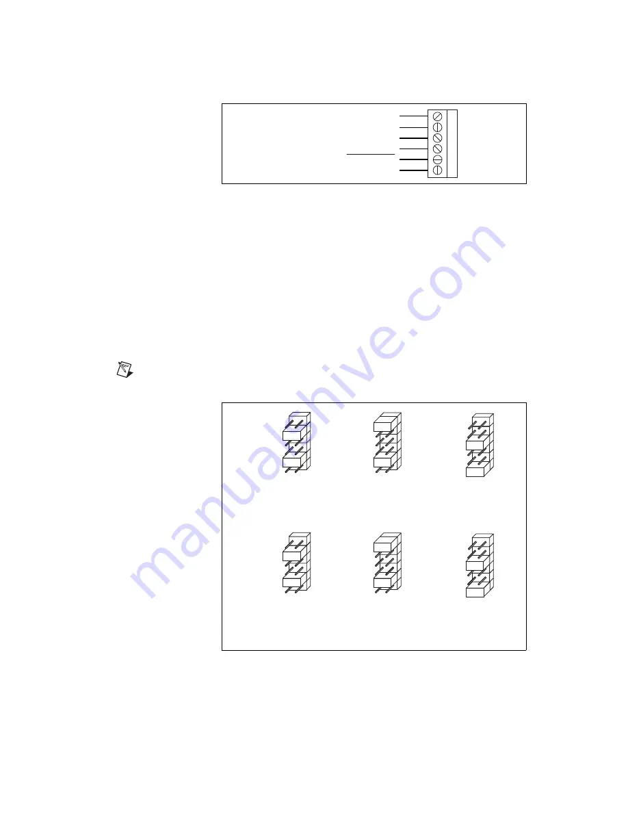
Figure 34.
UMI-Flex4 Axes Amplifier/Driver Terminal Block Pin Assignment
The Analog Output signals are used as command outputs to a servo
amplifier or as general-purpose voltage outputs. The Step and Dir signals
are used as command outputs to a stepper driver.
The Inhibit Output signals are used to disable the amplifier/driver for that
axis. The UMI combines the host bus interlock circuit, the per axis Inhibit
Input signals, and the per axis controller Inhibit Output to create the per
axis Inhibit Output signal. The host bus interlock monitors the +5 V pin
from the motion controller to verify that the controller is powered and
properly connected to the UMI. If the host bus interlock detects a problem,
or if the Inhibit Input signal or the controller Inhibit Output signal for that
axis is asserted, the Inhibit Output for that axis is asserted.
Note
You must configure the controller’s Inhibit Output signals as active-low for proper
operation of the inhibit circuitry.
Figure 35.
UMI-Flex4 Jumper Configuration
1
2
3
4
5
Analog Output or Step
Analog Output Ground or Dir
6
NC
+5 V (Output)
Digital Ground
Inhibit Output
Axis 3
Analog Output
Analog Output Ground
Axis 5
Analog Output
Analog Output Ground
Axis 5
Step
Dir
Axis 4
Analog Output
Analog Output Ground
Axis 6
Analog Output
Analog Output Ground
Axis 6
Step
Dir
JP2 Jumper Configuration for J15
JP3 Jumper Configuration for J16
Summary of Contents for UMI-4A
Page 35: ......


