


Chapter 2
Connecting the Signals
2-8
ni.com
Rear Signal Connector Descriptions
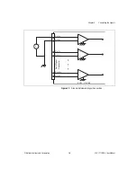
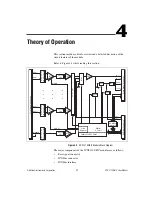
The rear signal connector on the cabled module is the interface between
the DAQ device and all modules in the SCXI chassis. CH 0 is used to
differentially multiplex all 32 channels, the CJ sensor, and analog signals
from the modules to the connected DAQ device.
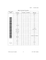
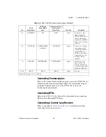
The communication signals between the DAQ device and the SCXI
system are listed in Table 2-4. If the DAQ device is connected to the
SCXI-1102/B/C, these digital lines are unavailable for general-purpose
digital I/O.
Table 2-4.
SCXI-1102/B/C Communication Signals
Pin
SCXI
Signal Name
NI-DAQmx
Device Signal
Name
Traditional NI-DAQ
(Legacy) Device
Signal Name
Direction
Description
24, 33
DIG GND
D GND
DGND
—
Digital ground—these
pins supply the
reference for
E/M Series DAQ device
digital signals and are
connected to the
module digital ground.
25
SER DAT IN
P0.0
DIO0
Input
Serial data in—this
signal taps into the
SCXIbus MOSI line to
send serial input data to
a module or Slot 0.
26
SER DAT OUT
P0.4
DIO4
Output
Serial data out—this
signal taps into the
SCXIbus MISO line to
accept serial output data
from a module.
27
DAQ D*/A
P0.1
DIO1
Input
Board data/address
line—this signal taps
into the SCXIbus D*/A
line to indicate to the
module whether the
incoming serial stream
is data or address
information.


