


©
National Instruments Corporation
5
SCXI-1353 Shielded Cable Assembly
3.
Insert the 50-pin female connector on the rear of the SCXI-1349 into
the rear signal connector of the SCXI module that passes analog
signals to the 100-pin E Series DAQ device.
4.
Screw the rear panel of the SCXI-1349 to the threaded strips in the rear
of the SCXI chassis to secure the adapter.
5.
Connect the end of the cable labeled
MIO-16
to the 68-pin connector
of the SCXI-1349.
6.
Insert the 50-pin female connector on the rear of the AI-48/DIO-24
into the rear signal connector of the SCXI module or feedthrough panel
that connects to pins 51–100 of the DAQ device.
7.
Screw the rear panel of the AI-48/DIO-24 to the threaded strips in the
rear of the SCXI chassis to secure the adapter.
8.
Connect the end of the cable labeled
EXTENDED I/O
to the 68-pin
connector of the AI-48/DIO-24.
9.
Connect the 100-pin end of the cable to the I/O connector of the DAQ
device.
10. Use the tie wraps to secure the cable to a fixed object to relieve the
strain on the cable. Strain relief is necessary because the SCXI-1353
has a long, stiff backshell that can exert leverage on the DAQ device
connector.
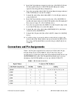
Connections and Pin Assignments
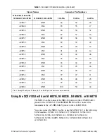
Table 1 lists the pin assignments for connections between the 100-pin
E Series DAQ device and the MIO-16 cable. Table 2 lists the pin
assignments for connections between the 100-pin E Series DAQ device and
the EXTENDED I/O cable. The 100-pin E Series DAQ device you use
determines which SCXI modules you can use with the SCXI-1353.
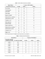
Table 1.
MIO-16 Cable Connections
Signal Names
Connector Pin Numbers
100-Pin E Series Device
100-Pin
50-Pin
68-Pin
AIGND
1, 2
1, 2
24, 27, 29, 32, 56, 59, 64, 67
ACH0
3
3
68
ACH8
4
4
34
ACH1
5
5
33
ACH9
6
6
66
ACH2
7
7
65


