


Each signal can only be used by one inverter at a time. For example, if SKiiP 3 GB half-bridge
inverter 0 is connected on J16, then connectors J36, J29, J26, and J24 cannot be used because
all of these connectors share several lines with J16.
The DC link voltage output can be connected to either simultaneous scanned analog input or
scanned analog input. Refer to the
Simultaneous Sampled Analog Input
on page 15 and
Scanned Analog Input
on page 24 sections for details about signal routing.
Note
By default, the inverter analog outputs are not connected to the GPIC analog
inputs. The onboard switches should be configured before using the sbRIO-9687
interface board.
Inverter CAN Bus Configuration
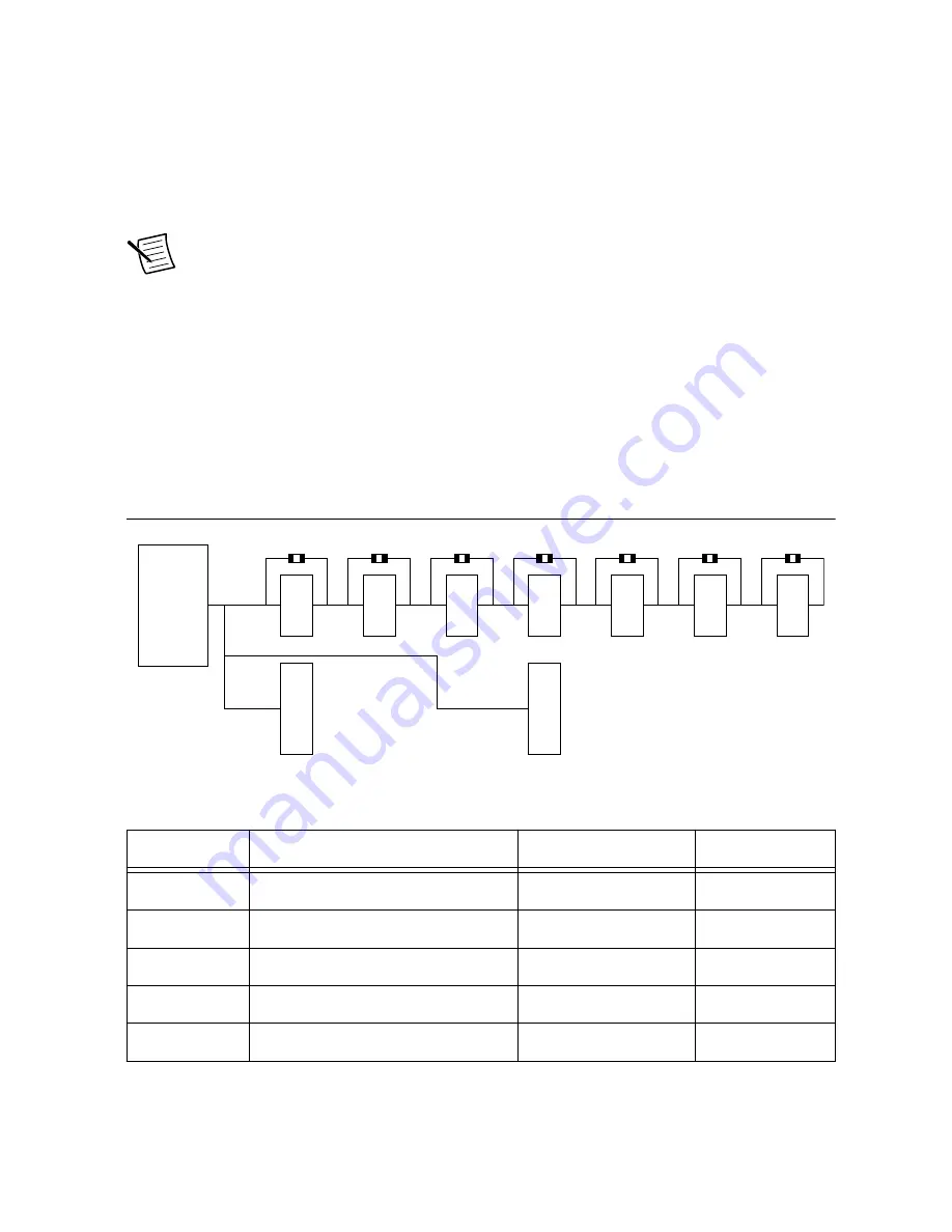
The SKiiP 4 inverters have a CAN port for easy diagnosis of the system. The inverters are
connected to CAN bus in order, with inverter 0 closest to the GPIC. If one of the SKiiP 4
inverters is not used, the corresponding switch should be closed for CAN bus continuity. The
switches should be open only when a SKiiP 4 inverter is connected to the corresponding
connector.
Figure 4. sbRIO-9687 CAN Bus Topology
GPIC
SKiiP 4
SKiiP 4
SKiiP 4
SKiiP 4
SKiiP 4
SKiiP 4
SKiiP 4
Semikube GD
Semikube GD
0
1
2
3
4
5
6
SW15
SW16
SW17
SW18
SW19
SW20
SW22
Table 8. SKiiP 4 Connector CAN Configuration
Inverter
Inverter Connector
CAN Switch
Contacts
0
J16
SW15
1, 2
1
J17
SW16
1, 2
2
J18
SW17
1, 2
3
J19
SW18
1, 2
4
J20
SW19
1, 2
12
|
ni.com
|
sbRIO-9687 User Manual


