
NI PXIe-1086 Getting Started Guide
|
© National Instruments
|
7
6.
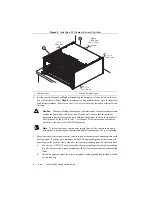
Connect the AC power source to the chassis before installing the system controller or
modules. The AC power cord grounds the chassis and protects it from electrical damage
while you install the system controller.
7.
Power on the chassis. Make sure the switch LED is steady green (not flashing), indicating
the chassis is powered on and operating normally. If it is not, refer to Chapter 2,
Installation
and Configuration,
of the
NI PXIe-1086 User Manual
for more information about LED
indicators.
8.
Power off the chassis.
Step 2: Install the Controller
Note
Be sure the chassis is connected to an AC power source before installing the
system controller. The AC power cord grounds the chassis and protects it from
electrical damage while you install the controller.
Caution
Refer to your PXI Express system controller user manual for specific
instructions and warnings.
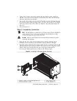
1.
Inspect the slot 1 pins on the chassis backplane for any bending or damage prior to
installation. Do not install the system controller if any pins are bent or damaged.
2.
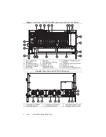
Install the system controller into the system controller slot (slot 1, indicated by the red card
guides) by first placing the system controller PCB into the front of the card guides (top and
bottom). Slide the system controller to the rear of the chassis, making sure the
injector/ejector handle is pushed down as shown in the following figure.
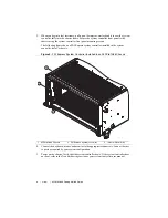
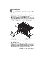
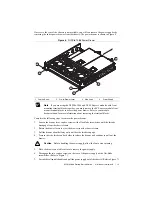
Figure 4.
Installing a PXI Express System Controller
1
System Controller Front Panel Mounting Screws (4x)
2
PXI Express System Controller
3
Injector/Ejector Handle
4
NI PXIe-1086 Chassis
NI
PX
Ie-
1086
3
2
1
4