
4
|
ni.com
|
NI PXIe-1086 Getting Started Guide
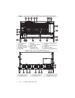
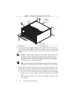
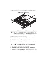
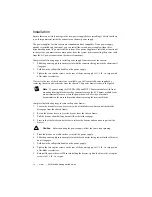
Figure 1.
Front View of the NI PXIe-1086 Chassis (with Optional Filler Panels)
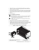
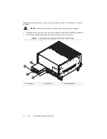
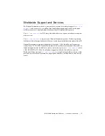
Figure 2.
Rear View of the NI PXIe-1086 Chassis
1
Power Inhibit Switch
2
Status LEDs
3
Inhibit/Fault Connector
4
Earth (Ground) Terminal
5
Backplane Connectors
6
Clk10 Output
7
Clk10 Input
8
PXI Filler Panels (Optional)
9
Removable Feet
10 Fan Door Latch
11 PXI Express Hybrid
Peripheral Slots (16x)
12 PXI Express PXI Express System
Timing Slot
13 PXI Express System Controller Slot
14 Ethernet Port
15 Chassis Carry Handle
16 System Controller Expansion Slots
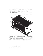
1
Power Supply Cooling Fan
2
Power Supply Handle
3
Chassis Power Connectors
4
Chassis Ground Screw
5
Inhibit Mode Selector Switch
6
Fan Speed Selector Switch
NI PXIe-1086
8
3
14
5
4
7
6
1
9
9
9
10
9
15
2
1
3
11
10
11
16
12
2
2
1
1
4
1
1
6
5
3


