


Chapter 1
Getting Started
1-4
ni.com
Chassis Description
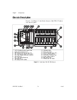
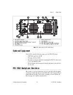
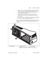
Figure 1-1 and Figure 1-2 show the key features of the PXI-1052 chassis
front and rear panels.
Figure 1-1.
Front View of the PXI-1052 Chassis
1
On/Off (Standby) System Power Switch
2
System Power Indicator LED
3
SCXI Subsystem Power Indicator LED
4
SCXI Low-Voltage Analog Bus Connector
5
SCXI High-Voltage Analog Bus Connector
6
PXI Filler Panel
7
SCXI High-Voltage Backplane
8
Removable Feet
9
SCXI Subsystem Backplane
10 SCXI Module Slots
11 PXI Peripheral Slots
12 PXI Star Trigger/Peripheral Slot
13 PXI System Controller Slot
14 PXI Controller Expansion Slots
15 PXI Subsystem Backplane
16 Removable Handle
17 PXI Backplane Connectors
NATIONAL
INSTRUMENTS
NI PXI-1052
LV ANALOG
BUS
300V CAT II
HV ANALOG
BUS
3
2
1
4
!
12
10
3
4
2
1
5
6
13
11
8
14
15
16
17
8
8
9
7
SCXI
POWER
SYSTEM
POWER


