background image

Appendix A

Specifications

©

 National Instruments Corporation

A-11

NI PXIe-1065 User Manual

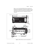
Figures A-1 and A-2 show the NI PXIe-1065 chassis dimensions. The 
holes shown are for the installation of the optional rack mount kits. You can 
install those kits on the front or rear of the chassis, depending on which end 
of the chassis you want to face toward the front of the instrument cabinet. 
Notice that the front and rear chassis mounting holes (size M4) are 
symmetrical.

Figure A-1.  

NI PXIe-1065 Chassis Dimensions (Front and Side)

0.57

(14.5)

Dimen

s

ion

s


a

re in inche

s

 (millimeter

s

)

0.

3

0 (7.25)

.

3

9

(9.9)

17.54 (445.6)

6.97

(177.1)

3

.54

(90.0)

1.

8

4

(46.

8

)

17.11 (4

3

4.6)

3

.19

(

8

1.1)

2.12

(5

3

.

8

)

1.5

8

(40.1)

1.14

(29.1)

1.

3

7

(

3

4.

8

)

10.21 (259.1)

1

8

17

16

15

1

3

12

11

10

9

8

7

6

5

4

3

2

NI PXIe-1065

1

H

14

H

H

H

1.

8

2

(46.

3

)

1.

8

2

(46.

3

)

Front of

PXI C

a

rd

Summary of Contents for PXI Express NI PXIe-1065

Page 1: ...PXI Express TM NI PXIe 1065 User Manual NI PXIe 1065 User Manual December 2008 371990B 01 ...

Page 2: ...ebanon 961 0 1 33 28 28 Malaysia 1800 887710 Mexico 01 800 010 0793 Netherlands 31 0 348 433 466 New Zealand 0800 553 322 Norway 47 0 66 90 76 60 Poland 48 22 328 90 10 Portugal 351 210 311 210 Russia 7 495 783 6851 Singapore 1800 226 5886 Slovenia 386 3 425 42 00 South Africa 27 0 11 805 8197 Spain 34 91 640 0085 Sweden 46 0 8 587 895 00 Switzerland 41 56 2005151 Taiwan 886 02 2377 2222 Thailand ...

Page 3: ...g storing in an information retrieval system or translating in whole or in part without the prior written consent of National Instruments Corporation National Instruments respects the intellectual property of others and we ask our users to do the same NI software is protected by copyright and other intellectual property laws Where NI software may be used to reproduce software or other materials be...

Page 4: ...bility with CompactPCI 1 6 System Controller Slot 1 6 Hybrid Peripheral Slots 1 7 PXI Peripheral Slots 1 7 PXI Express Peripheral Slots 1 8 System Timing Slot 1 8 PXI Local Bus 1 9 PXI Trigger Bus 1 10 System Reference Clock 1 11 PXIe_SYNC_CTRL 1 14 Chapter 2 Installation and Configuration Safety Information 2 1 Chassis Cooling Considerations 2 2 Providing Adequate Clearance 2 2 Chassis Ambient Te...

Page 5: ...13 Trigger Configuration in MAX 2 14 PXI Trigger Bus Routing 2 15 Using System Configuration and Initialization Files 2 16 Chapter 3 Maintenance Service Interval 3 1 Preparation 3 1 Cleaning 3 1 Interior Cleaning 3 1 Exterior Cleaning 3 2 Resetting the AC Mains Circuit Breaker 3 2 Replacing the Modular Power Supply 3 3 Removal 3 3 Installation 3 3 Configuration 3 4 Connecting Safety Ground 3 4 Con...

Page 6: ...ake to avoid injury data loss or a system crash When this symbol is marked on the product refer to the Read Me First Safety and Radio Frequency Interference document shipped with the product for precautions to take bold Bold text denotes items that you must select or click in the software such as menu items and dialog box options Bold text also denotes parameter names italic Italic text denotes va...

Page 7: ...Specifications for Microcomputers Using IEC 603 2 Connectors IEEE 1101 10 IEEE Standard for Additional Mechanical Specifications for Microcomputers Using IEEE 1101 1 Equipment Practice PICMG EXP 0 R1 0 CompactPCI Express Specification PCI Industrial Computers Manufacturers Group PCI Express Base Specification Revision 1 1 PCI Special Interest Group PXI 5 PXI Express Hardware Specification Revision...

Page 8: ...are and switches are undamaged Inspect the inner chassis for any possible damage debris or detached components If damage appears to have been caused during shipment file a claim with the carrier Retain the packing material for possible inspection and or reshipment What You Need to Get Started The NI PXIe 1065 chassis kit contains the following items NI PXIe 1065 chassis Filler panels AC power cabl...

Page 9: ...e Specification offering advanced timing and synchronization features The key features of the NI PXIe 1065 chassis include the following High Performance for Instrumentation Requirements Up to 1 GB s single direction per PXI Express slot dedicated bandwidth x4 PCIe 30 W per slot cooling meets increased PXIe cooling requirements Low jitter internal 10 MHz reference clock for PXI slots with 25 ppm s...

Page 10: ... extended temperature range Power supply temperature and fan monitoring HALT tested for increased reliability Field replaceable power supply shuttle Multi Chassis Support PXIe System Timing Slot for tight synchronization across chassis Rear CLK10 I O connectors Switchless CLK10 routing Optional Features Front and rear rack mount kits Replacement power supply shuttle EMC filler panels Slot blockers...

Page 11: ...w of the NI PXIe 1065 Chassis 1 Chassis Carry Handle 2 Backplane Connectors 3 PXI Filler Panels 4 Chassis Model Name 5 Removable Feet 6 PXI Peripheral Slots 9x 7 PXI Express System Timing Slot 8 PXI Express Hybrid Peripheral Slots 4x 9 PXI Express Peripheral Slots 3x 10 PXI Express System Controller Slot 11 Power Inhibit Switch 12 Power Inhibit Switch LED 13 System Controller Expansion Slots 18 17...

Page 12: ...n the front of the chassis The second option is a rear rack mount kit The rear rack mount kit differs from the front kit to allow for easier installation into the rack For more information refer to Figure A 3 NI Chassis Rack Mount Kit Components 1 Universal AC Input 2 Push Reset Circuit Breaker 3 Chassis Ground Screw 4 Fan Guard Retainer Screws 5 Power Supply Shuttle ID Label 6 10 MHz REF OUT BNC ...

Page 13: ... and is a 4 Link configuration system slot as defined by the CompactPCI Express and PXI Express specifications It has three system controller expansion slots for system controller modules that are wider than one slot These slots allow the system controller to expand to the left to prevent the system controller from using peripheral slots The backplane routes a x4 PCI Express link from the system c...

Page 14: ...h a switch to the system slot A CompactPCI Express Type 2 Peripheral with x4 or x1 PCI Express link to the system slot or through a switch to the system slot A hybrid compatible PXI Peripheral module that has been modified by replacing the J2 connector with an XJ4 connector installed in the upper eight rows of J2 Refer to the PXI Express Specification for details The PXI Peripheral communicates th...

Page 15: ... slot through a PCIe switch A CompactPCI Express Type 2 Peripheral with x4 or x1 PCI Express link to the system slot through a PCIe switch The system timing slot has 3 dedicated differential pairs PXIe_DSTAR connected from the TP1 and TP2 connectors to the XP3 connector for each PXI Express peripheral or hybrid peripheral slot as well as routed back to the XP3 connector of the system timing slot a...

Page 16: ... to Figure 1 4 for details The left local bus 6 from slot 1 is not routed anywhere and the right local bus signals from slot 18 are not routed anywhere P2 P1 XP4 XP3 TP2 TP1 P2 P1 P2 P1 P2 P1 P1 P1 P1 XP4 XP3 XP4 XP3 XP4 XP3 XP4 XP3 XP4 XP3 XP4 XP3 XP4 XP3 P2 P1 P2 P1 P2 P1 P2 P1 P2 P1 P1 XP4 XP3 XP2 XP1 PXIe_DSTAR 11 PXIe_DSTAR 8 PXIe_DSTAR 6 PXIe_DSTAR 5 PXIe_DSTAR 3 PXIe_DSTAR 2 PXIe_DSTAR 1 PX...

Page 17: ...Modules can pass triggers to one another allowing precisely timed responses to asynchronous external events the system is monitoring or controlling The PXI trigger lines from adjacent PXI trigger bus segments can be routed in either direction across the PXI trigger bridges through buffers This allows you to send trigger signals to and receive trigger signals from every slot in the chassis Static t...

Page 18: ... use this common reference clock signal to synchronize multiple modules in a measurement or control system An independent buffer drives PXIe_CLK100 to the PXI Express peripheral slots hybrid peripheral slots and system timing slot Refer to Figure 1 5 for the routing configuration of PXIe_CLK100 These clocks are matched in skew to less than 100 ps The differential pair must be terminated on the per...

Page 19: ...r to Table B 8 XP4 Connector Pinout for the System Timing Slot for the pinout When a 10MHz clock is detected on this pin the backplane automatically phase locks the PXI_CLK10 PXIe_CLK100 and PXIe_SYNC100 signals to this external clock and distributes these P2 P1 XP4 XP3 TP2 TP1 P2 P1 P2 P1 P2 P1 P1 P1 P1 XP4 XP3 XP4 XP3 XP4 XP3 XP4 XP3 XP4 XP3 XP4 XP3 XP4 XP3 P2 P1 P2 P1 P2 P1 P2 P1 P2 P1 XP4 XP3 ...

Page 20: ..._IN pin of the System Timing Slot and the 10 MHz REF IN connector on the rear of the chassis the signal on the System Timing Slot is selected Refer to Table 1 2 which explains how the 10 MHz clocks are selected by the backplane A copy of the backplane s PXI_CLK10 is exported to the 10 MHz REF OUT connector on the rear of the chassis This clock is driven by an independent buffer Refer to Appendix A...

Page 21: ...stem timing slot has a control pin for PXIe_SYNC100 called PXIe_SYNC_CTRL for use when n 1 Refer to Table B 7 XP3 Connector Pinout for the System Timing Slot for system timing slot pinout Refer to Appendix A Specifications for the PXIe_SYNC_CTRL input specifications By default a high level detected by the backplane on the PXIe_SYNC_CTRL pin causes a synchronous restart for the PXIe_SYNC100 signal ...

Page 22: ...nection from the premise wire safety ground to the chassis ground The earth safety ground must be connected during use of this equipment to minimize shock hazards Refer to the Connecting Safety Ground section for instructions on connecting safety ground Live Circuits Operating personnel and service personnel must not remove protective covers when operating or servicing the chassis Adjustments and ...

Page 23: ...is is designed to operate on a bench or in an instrument rack Regardless of the configuration you must provide the cooling clearances as outlined in the following sections Providing Adequate Clearance The primary cooling exhaust vent for the NI PXIe 1065 is on the top of the chassis The primary intake vent is on the rear of the chassis The secondary intake and exhaust vents are located along the s...

Page 24: ... National Instruments Corporation 2 3 NI PXIe 1065 User Manual Figure 2 1 NI PXIe 1065 Cooling Clearances 18 17 16 15 13 12 11 10 9 8 7 6 5 4 3 2 NI PXIe 1065 1 H 14 H H H 1 75 44 45 1 75 44 45 3 00 76 20 Dimensions are in inches millimeters ...

Page 25: ...e of this the chassis ambient temperature is defined as the temperature that exists just outside of the fan intake vents on the rear of the chassis Note that this temperature may be higher than ambient room temperature depending on the surrounding equipment and or blockages present It is the user s responsibility to ensure that this ambient temperature does not exceed the 1 Primary Air Exhaust Ven...

Page 26: ...rovided with the chassis in unused or empty slots Secure with the captive mounting screws provided Installing Slot Blockers The cooling performance of the chassis can be improved by installing optional slot blockers Refer to ni com for more details Rack Mounting Rack mount applications require the optional rack mount kits available from National Instruments Refer to the instructions supplied with ...

Page 27: ...ew of the NI PXIe 1065 Chassis to locate the AC inlet The Inhibit Mode switch allows you to power on the chassis or place it in standby mode Set the Inhibit Mode switch on the back of the chassis to the Manual position Observe that all fans become operational and the power switch LED is a steady green Switching the Inhibit Mode switch to the Default position allows the system controller to control...

Page 28: ...ntroller fully into the chassis frame Secure the system controller front panel to the chassis using the system controller front panel mounting screws 4 Connect the keyboard mouse and monitor to the appropriate connectors Connect devices to ports as required by your system configuration 5 Power on the chassis Verify that the system controller boots If the system controller does not boot refer to yo...

Page 29: ...Figure 2 4 NI PXI Express System Controller Installed in a NI PXIe 1065 Chassis Installing Peripheral Modules Caution The NI PXIe 1065 chassis has been designed to accept a variety of peripheral module types in different slots To prevent damage to the chassis ensure that the peripheral module is being installed into a slot designed to accept it Refer to Chapter 1 Getting Started for a description ...

Page 30: ...wered off 3 Install a module into a chassis slot by first placing the module card PCB into the front of the card guides top and bottom as shown in Figure 2 5 Slide the module to the rear of the chassis making sure that the injector ejector handle is pushed down as shown in Figure 2 5 4 When you begin to feel resistance push up on the injector ejector handle to fully seat the module into the chassi...

Page 31: ...ion requirements If the inhibit switch LED is steady red the system fans or power supply fan has failed The remaining fans will automatically be driven high Note If two system fans or both of the power supply fans fail the chassis will shut down automatically preventing the chassis and modules from damage due to overheating Remote Voltage Monitoring and Control The NI PXIe 1065 chassis supports re...

Page 32: ...diagram of the remote voltage monitoring connector Connect the reference lead of the voltmeter to one of the ground pins Compare each voltage reading to the values listed in Table 2 2 Note Use the rear panel 9 pin D SUB connector to check voltages only Do not use the connector to supply power to external devices If the voltages fall within the specified ranges the chassis complies with the Compact...

Page 33: ...l remain off standby when you remove this connection the chassis turns on Note For the Remote Inhibit signal to control the On Off standby state of the chassis the Inhibit Mode switch must be in the Manual position PXI_CLK10 Rear Connectors There are two BNC connectors on the rear of the NI PXIe 1065 chassis for PXI_CLK10 The connectors are labeled IN and OUT You can use them for supplying the bac...

Page 34: ... The configuration steps for single or multiple chassis systems are the same Figure 2 6 Multichassis Configuration in MAX PXI 1 System Configuration 1 Launch MAX 2 In the Configuration tree click the Devices and Interfaces branch to expand it 3 If the PXI system controller has not yet been configured it is labeled PXI System Unidentified Right click this entry to display the pop up menu then selec...

Page 35: ...hassis manufacturer The information in this file is combined with information about the system controller to create a single PXI 1 system initialization file called pxisys ini PXI System Initialization The NI system controller uses MAX to generate the pxisys ini file from the chassis ini file Device drivers and other utility software read the pxiesys ini and pxisys ini file to obtain system inform...

Page 36: ...rs within the same chassis using the Trigger Routing tab in MAX as shown in Figure 2 6 Note Selecting any non disabled routing automatically reserves the line in all trigger buses being routed to If you are using NI DAQmx it will reserve and route trigger lines for you so you won t have to route trigger lines manually Complete the following steps to configure trigger routings in MAX 1 In the Confi...

Page 37: ...formation about the system controller to create a single system initialization file called pxisys ini PXI System Initialization The system controller manufacturer either provides a pxisys ini file for the particular chassis model that contains the system controller or provides a utility that can read an arbitrary chassis ini file and generate the corresponding pxisys ini file System controllers fr...

Page 38: ...fore attempting any procedures in this chapter Caution Many components within the chassis are susceptible to static discharge damage Service the chassis only in a static free environment Observe standard handling precautions for static sensitive devices while servicing the chassis Always wear a grounded wrist strap or equivalent while servicing the chassis Cleaning Cleaning procedures consist of e...

Page 39: ...ts Resetting the AC Mains Circuit Breaker If the NI PXIe 1065 chassis is connected to an AC source and encounters an over current condition the circuit breaker on the rear panel will trip to prevent damage to the chassis Complete the following steps to reset the circuit breaker 1 Turn off the chassis 2 Disconnect the AC power cable 3 Depress the circuit breaker to reset it 4 Reconnect the AC power...

Page 40: ...luded with the kit Removal The NI PXIe 1065 AC power supply is a replacement part for the NI PXIe 1065 AC chassis Before attempting to replace the power supply shuttle verify that there is adequate clearance behind the chassis Disconnect the power cable from the power supply shuttle on the back of the chassis Identify the ten mounting screws for the NI PXIe 1065 that attach the power supply shuttl...

Page 41: ...is to locate the fan speed selector Select High for maximum cooling performance recommended or Auto for quieter operation Set the Inhibit Mode switch to the Default position Connecting Safety Ground Refer to the Connecting Safety Ground section of Chapter 2 Installation and Configuration Connecting to Power Source Refer to the Connecting to Power Source section of Chapter 2 Installation and Config...

Page 42: ...ing frequency range1 47 to 63 Hz Input current rating 10 5 A Over current protection 12 A circuit breaker Line regulation 3 3 V 0 2 5 V 0 1 12 V 0 1 Efficiency 70 typical Power disconnect The AC power cable provides main power disconnect The front panel power switch causes the internal chassis power supply to provide DC power to the CompactPCI PXI Express backplane You also can use the rear panel ...

Page 43: ...rrent capacity Load regulation Voltage Maximum Current 3 3 V 61 A 5 V 56 A 12 V 45 A 12 V 4 A 5 VAUX 1 5 A Slot 5 V V I O 3 3 V 12 V 12 V 5 VAUX System Controller Slot 9 A 0 A 9 A 11 A 0 A 1 A System Timing Slot 0 A 0 A 3 A 2 A 0 A 1 A Hybrid Peripheral Slot with PXI 1 Peripheral 6 A 5 A 6 A 1 A 1 A 0 A Hybrid Peripheral Slot with PXI 5 Peripheral 0 A 0 A 3 A 3 A 0 A 1 A PXI 1 Peripheral Slot 6 A ...

Page 44: ...assis Cooling Module cooling system NI PXIe 1065 Forced air circulation positive pressurization through three 165 cfm fans with High Auto speed selector Slot airflow direction Bottom of module to top of module Module cooling intake Bottom rear of chassis Module cooling exhaust Along both sides and top of chassis Power supply cooling system Forced air circulation through two integrated fans Power s...

Page 45: ...8800F Class 2 high temperature limit Relative humidity range 10 to 90 noncondensing Tested in accordance with IEC 60068 2 56 Storage Environment Ambient temperature range 40 to 71 C Tested in accordance with IEC 60068 2 1 and IEC 60068 2 2 Meets MIL PRF 28800F Class 3 limits Relative humidity range 5 to 95 noncondensing Tested in accordance with IEC 60068 2 56 Shock and Vibration Operational shock...

Page 46: ...ipment for measurement control and laboratory use IEC 61010 1 EN 61010 1 UL 61010 1 CSA 61010 1 Note For UL and other safety certifications refer to the product label or the Online Product Certification section Electromagnetic Compatibility This product is designed to meet the requirements of the following standards of EMC for electrical equipment for measurement control and laboratory use EN 6132...

Page 47: ... an environmentally responsible manner NI recognizes that eliminating certain hazardous substances from our products is beneficial not only to the environment but also to NI customers For additional environmental information refer to the NI and the Environment Web page at ni com environment This page contains the environmental regulations and directives with which NI complies as well as other envi...

Page 48: ...rs Conforms to IEC 917 and IEC 1076 4 101 and are UL 94 V 0 rated System Synchronization Clocks PXI_CLK10 PXIe_CLK100 PXIe_SYNC100 10 MHz System Reference Clock PXI_CLK10 Maximum slot to slot skew 1 ns Accuracy 25 ppm max guaranteed over the operating temperature range Maximum jitter 5 ps RMS phase jitter 10 Hz 1 MHz range Duty factor 45 55 Unloaded signal swing 3 3 V 0 3 V Note For other specific...

Page 49: ...ress Hardware Specification External 10 MHz Reference Out BNC on rear panel of chassis Accuracy 25 ppm max guaranteed over the operating temperature range Maximum jitter 5 ps RMS phase jitter 10 Hz 1 MHz range Output amplitude 1 VPP 20 square wave into 50 Ω 2 VPP unloaded Output impedance 50 Ω 5 Ω External Clock Source Frequency 10 MHz 100 PPM Input amplitude Rear panel BNC 200 mVPP to 5 VPP squar...

Page 50: ...B PXIe DSTARC Maximum slot to slot skew 150 ps Maximum differential skew 25 ps Backplane differential impedance 100 Ω 10 Note For PXIe slot to PXI_DSTAR mapping refer to the System Timing Slot section of Chapter 1 Getting Started For other specifications the NI PXIe 1065 complies with the PXI 5 PXI Express Hardware Specification Mechanical Overall dimensions Standard chassis Height 6 97 in 177 1 m...

Page 51: ... Weight 12 8 kg 28 2 lb Chassis materials Sheet Aluminum 5052 H32 3003 H14 and 6061 T6 Extruded Aluminum 6060 T6 and Cold Rolled Steel PC ABS Santoprene Nylon Finish Conductive Clear Iridite on Aluminum Electroplated Nickel on Cold Rolled Steel Polyurethane Enamel ...

Page 52: ...ich end of the chassis you want to face toward the front of the instrument cabinet Notice that the front and rear chassis mounting holes size M4 are symmetrical Figure A 1 NI PXIe 1065 Chassis Dimensions Front and Side 0 57 14 5 Dimensions are in inches millimeters 0 30 7 25 39 9 9 17 54 445 6 6 97 177 1 3 54 90 0 1 84 46 8 17 11 434 6 3 19 81 1 2 12 53 8 1 58 40 1 1 14 29 1 1 37 34 8 10 21 259 1 ...

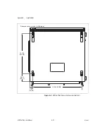
Page 53: ...Appendix A Specifications NI PXIe 1065 User Manual A 12 ni com Figure A 2 NI PXIe 1065 Chassis Dimensions Bottom 1 017 25 83 2 524 64 11 15 504 393 8 12 700 322 58 Dimensions are in inches millimeters ...

Page 54: ...ure A 3 shows the chassis rack mount kit components Figure A 3 NI Chassis Rack Mount Kit Components Note The chassis shown in Figure A 3 is representative of the NI PXI 1044 1045 and NI PXIe 1065 product line 1 Front Rack Mount Kit 2 NI Chassis 3 Optional Rear Rack Mount Kit 3 NI PXIe 1065 2 1 ...

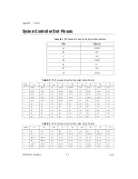
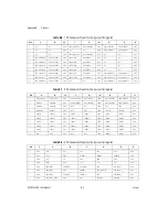
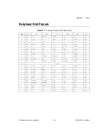
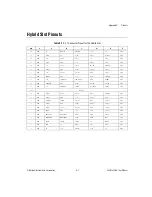
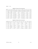
Page 55: ... Table B 6 shows the TP2 Connector Pinout for the System Timing slot Table B 7 shows the XP3 Connector Pinout for the System Timing slot Table B 8 shows the XP4 Connector Pinout for the System Timing slot Table B 9 shows the P1 connector pinout for the peripheral slots Table B 10 shows the P2 connector pinout for the peripheral slots Table B 11 shows the P1 connector pinout for the Hybrid peripher...

Page 56: ...4PERp2 4PERn2 GND 4PERp1 4PERn1 GND 5 4PETp3 4PETn3 GND 4PERp3 4PERn3 GND RSV RSV GND 6 RSV RSV GND RSV RSV GND RSV RSV GND 7 RSV RSV GND RSV RSV GND RSV RSV GND 8 RSV RSV GND RSV RSV GND RSV RSV GND 9 RSV RSV GND RSV RSV GND RSV RSV GND 10 RSV RSV GND RSV RSV GND RSV RSV GND Table B 3 XP3 Connector Pinout for the System Controller Slot Pin A B ab C D cd E F ef 1 RSV RSV GND RSV RSV GND RSV RSV GN...

Page 57: ...LK10 GND 7 GND PXI_TRIG1 PXI_TRIG0 RSV GND PXI_TRIG7 GND 8 GND RSV GND RSV RSV PXI_LBR6 GND Table B 5 TP1 Connector Pinout for the System Timing Slot Pin A B ab C D cd E F ef 1 PXIe_DSTARA3 PXIe_DSTARA3 GND NC NC GND NC NC GND 2 PXIe_DSTARC4 PXIe_DSTARC4 GND PXI_STAR12 PXI_STAR13 GND NC NC GND 3 PXIe_DSTARB4 PXIe_DSTARB4 GND NC NC GND NC NC GND 4 PXIe_DSTARA4 PXIe_DSTARA4 GND NC NC GND NC NC GND 5...

Page 58: ... Pinout for the System Timing Slot Pin A B ab C D cd E F ef 1 PXIe_CLK100 PXIe_CLK100 GND PXIe_SYNC100 PXIe_SYNC100 GND PXIe_DSTARC PXIe_DSTARC GND 2 PRSNT PWREN GND PXIe_DSTARB PXIe_DSTARB GND PXIe_DSTARA PXIe_DSTARA GND 3 SMBDAT SMBCLK GND RSV RSV GND RSV RSV GND 4 MPWRGD PERST GND RSV RSV GND 1RefClk 1RefClk GND 5 1PETp0 1PETn0 GND 1PERp0 1PERn0 GND 1PETp1 1PETn1 GND 6 1PETp2 1PETn2 GND 1PERp2 ...

Page 59: ...3 3V AD 15 AD 14 GND AD 13 GND 18 GND SERR GND 3 3V PAR C BE 1 GND 17 GND 3 3V IPMB_SCL IPMB_SDA GND PERR GND 16 GND DEVSEL GND V I O STOP LOCK GND 15 GND 3 3V FRAME IRDY BD_SEL TRDY GND 12 14 Key Area 11 GND AD 18 AD 17 AD 16 GND C BE 2 GND 10 GND AD 21 GND 3 3V AD 20 AD 19 GND 9 GND C BE 3 IDSEL AD 23 GND AD 22 GND 8 GND AD 26 GND V I O AD 25 AD 24 GND 7 GND AD 30 AD 29 AD 28 GND AD 27 GND 6 GND...

Page 60: ...K10 GND 16 GND PXI_TRIG1 PXI_TRIG0 RSV GND PXI_TRIG7 GND 15 GND PXI_BRSVA15 GND RSV PXI_LBL6 PXI_LBR6 GND 14 GND RSV RSV RSV GND RSV GND 13 GND RSV GND V I O RSV RSV GND 12 GND RSV RSV RSV GND RSV GND 11 GND RSV GND V I O RSV RSV GND 10 GND RSV RSV RSV GND RSV GND 9 GND RSV GND V I O RSV RSV GND 8 GND RSV RSV RSV GND RSV GND 7 GND RSV GND V I O RSV RSV GND 6 GND RSV RSV RSV GND RSV GND 5 GND RSV G...

Page 61: ...V AD 15 AD 14 GND AD 13 GND 18 GND SERR GND 3 3V PAR C BE 1 GND 17 GND 3 3V IPMB_SCL IPMB_SDA GND PERR GND 16 GND DEVSEL GND V I O STOP LOCK GND 15 GND 3 3V FRAME IRDY BD_SEL TRDY GND 12 14 Key Area 11 GND AD 18 AD 17 AD 16 GND C BE 2 GND 10 GND AD 21 GND 3 3V AD 20 AD 19 GND 9 GND C BE 3 IDSEL AD 23 GND AD 22 GND 8 GND AD 26 GND V I O AD 25 AD 24 GND 7 GND AD 30 AD 29 AD 28 GND AD 27 GND 6 GND RE...

Page 62: ... 1PETn2 GND 1PERp2 1PERn2 GND 1PERp1 1PERn1 GND 7 1PETp3 1PETn3 GND 1PERp3 1PERn3 GND 1PETp4 1PETn4 GND 8 1PETp5 1PETn5 GND 1PERp5 1PERn5 GND 1PERp4 1PERn4 GND 9 1PETp6 1PETn6 GND 1PERp6 1PERn6 GND 1PETp7 1PETn7 GND 10 RSV RSV GND RSV RSV GND 1PERp7 1PERn7 GND Table B 13 XP4 Connector Pinout for the Hybrid Slot Pin Z A B C D E F 1 GND GA4 GA3 GA2 GA1 GA0 GND 2 GND 5Vaux GND SYSEN WAKE ALERT GND 3 ...

Page 63: ...d Service Program Membership This program entitles members to direct access to NI Applications Engineers via phone and email for one to one technical support as well as exclusive access to on demand training modules via the Services Resource Center NI offers complementary membership for a full year after purchase after which you may renew to continue your benefits For information about other techn...

Page 64: ...ompatibility EMC and product safety You can obtain the DoC for your product by visiting ni com certification If you searched ni com and could not find the answers you need contact your local office or NI corporate headquarters Phone numbers for our worldwide offices are listed at the front of this manual You also can visit the Worldwide Offices section of ni com niglobal to access the branch offic...

Page 65: ... pico 10 12 n nano 10 9 μ micro 10 6 m milli 10 3 k kilo 103 M mega 106 G giga 109 T tera 1012 Symbols Degrees Equal or greater than Equal or less than Percent A A Amperes AC Alternating current ANSI American National Standards Institute Auto Automatic fan speed control AWG American Wire Gauge ...

Page 66: ...quiring a more robust mechanical form factor than desktop PCI It uses industry standard mechanical components and high performance connector technologies to provide an optimized system intended for rugged applications It is electrically compatible with the PCI Specification which enables low cost PCI components to be utilized in a mechanical form factor suited for rugged environments CSA Canadian ...

Page 67: ...dule front panel used to fill empty slots in the chassis G g 1 grams 2 a measure of acceleration equal to 9 8 m s2 GPIB General Purpose Interface Bus IEEE 488 gRMS A measure of random vibration The root mean square of acceleration levels in a random vibration test profile H hr Hours Hz Hertz cycles per second I IEC International Electrotechnical Commission an organization that sets international e...

Page 68: ...maximum steady state percentage that a DC voltage output will change as a result of a specified change in input AC voltage step change from 90 to 132 VAC or 180 to 264 VAC load regulation The maximum steady state percentage that a DC voltage output will change as a result of a step change from no load to full load output current M m Meters MHz Megahertz One million Hertz one Hertz equals one cycle...

Page 69: ... Deviation in signal transmission times slot blocker An assembly installed into an empty slot to improve the airflow in adjacent slots standby The backplane is unpowered off but the chassis is still connected to AC power mains System controller A module configured for installation in Slot 1of a PXI chassis This device is unique in the PXI system in that it performs the system controller functions ...

Page 70: ...ltiple modules in a measurement or control system The 10 MHz REF IN and OUT BNC connectors on the rear of the chassis can be used to synchronize multiple chassis to one reference clock The PXI backplane specification defines implementation guidelines for PXI_CLK10 System Timing slot This slot is located at slot 4 and has dedicated trigger lines to other slots T TTL Transistor transistor logic U UL...

Page 71: ...lation figure 2 4 clearances for chassis cooling 2 2 figure 2 3 CLK10 rear connectors 2 12 CompactPCI interoperability with NI PXIe 1065 backplane 1 6 configuration in MAX figure 2 13 configuration See installation configuration and operation connector pinouts See pinouts conventions used in the manual vii cooling air cooling of PXIe 1065 chassis 2 2 filler panel installation 2 5 setting fan speed...

Page 72: ... PXI Express system controller installed in a NI PXIe 1065 chassis figure 2 8 PXI 1 configuration in MAX 2 13 rack mounting 2 5 remote voltage monitoring and inhibiting interface 2 10 setting fan speed 2 5 site considerations 2 2 slot blocker installation 2 5 testing power up 2 6 unpacking the PXIe 1065 1 1 installing a PXI Express system controller figure 2 7 instrument drivers NI resources C 1 i...

Page 73: ...9 connector table 2 10 power cables table 1 2 power inhibit switch LED indicator 2 10 power supply connecting to 2 6 remote voltage monitoring and inhibiting interface 2 10 replacing 3 3 configuration 3 4 connecting safety ground 3 4 connecting to power source 3 4 installation 3 3 removal 3 3 voltages at voltage monitoring connector DB 9 table 2 10 power up testing 2 6 programming examples NI reso...

Page 74: ...nt A 4 storage environment A 4 environmental management A 6 WEEE information A 6 external clock source A 8 mechanical A 9 online product certification A 6 PXI differential star triggers PXIe DSTARA PXIe DSTARB PXIe DSTARC A 9 PXI star trigger A 9 PXIe_SYNC_CTRL A 9 rack mount kit dimensions figure A 13 safety A 5 shock and vibration A 4 system reference clocks A 7 static discharge damage caution 3...

Page 75: ...Corporation I 5 NI PXIe 1065 User Manual U unpacking the NI PXIe 1065 chassis 1 1 V voltage monitoring connector See DB 9 connector voltages at voltage monitoring connector DB 9 table 2 11 W Web resources C 1 WEEE information A 6 ...

Reviews: