background image

Getting Started with NI 7340/7350 Controllers and AKD Drives

|

© National Instruments

|

13

The UMI-7764 to AKD Drive Cable contains the following connections:

UMI-7764 Screw Terminal Leads

—Pigtail wire leads labeled with UMI-7764 signal 

names.

X8 10-Pin Connector

—10-pin connector containing the servo command, enable, and 

fault signals.

X9 DSUB Connector

—9-pin DSUB connector containing emulated encoder output 

signals from the AKD servo drive.

X1 3-pin Connector

—+24 V power supply connection for the AKD servo drive. 

+24V Power Supply Leads

—+24 V power supply leads.

3.

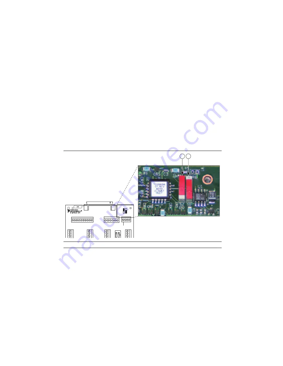
Configure the UMI-7764 DIP switches. You must set the DIP switches to the following 
settings to match the polarity configuration for the AKD servo drive:

Inhibit Input (S2)—Active High

Inhibit Output (S1)—Active Low

The UMI-7764 DIP switch configuration is shown in Figure 7.

Figure 7.  

UMI-7764 Inhi

b

it Input and Inhi

b

it Output DIP Switch Settings

4.

Connect an ex5 V power supply to the UMI-7764 Power Input Terminal Block. This 
connection is required to power the encoder circuitry that converts differential encoder 
signals to single-ended signals for the motion controller, as well as to power the UMI-7764 
Inhibit Output signals.

1

Inhi

b

it Input Polarity Switch (S2)

2

Inhi

b

it Output Polarity Switch (S1)

1

BP4

BP3

BP2

BP1

GND

+5 V

TRIG4

TRIG3

TRIG2

TRIG1

ASSY1

8

6343A-01

UMI-7764

FWDLIM1

HOME1

REVLIM1

AXIS1

FWDLIM3

HOME3

REVLIM3

AXIS3

AIGND

AREF

AIN4

AIN3

AIN2

AIN1

FWDLIM2

HOME2

REVLIM2

AXIS2

FWDLIM4

HOME4

REVLIM4

AXIS4

GND

NC1

SHUTDO

WN

INH ALL

S2 S1

ACTIVE HIGH

LO
W

2

Summary of Contents for PXI-7358

Page 1: ...PXI 7358...

Page 2: ...and Installation 8 Step 1 Connect and Configure the NI UMI 8 Step 2 Mount the Drive and Connect the Protective Earth 14 Step 3 Connect the NI UMI to AKD Cable to the AKD Servo Drive 15 Step 4 Connect...

Page 3: ...ing items to get started Hardware A computer with an available PXI or PCI slot NI 7340 or NI 7350 motion controller UMI 7764 or UMI 7772 74 68 pin cable to connect your NI UMI and motion controller UM...

Page 4: ...Visual C Microsoft Visual Basic AKD WorkBench software Figures 1 and 2 show the hardware connections using a UMI 7772 74 and UMI 7764 respectively Figure 1 UMI 7772 74 to AKD Drive Connections Host PC...

Page 5: ...designing a basic move designing a multi axis move incorporating image and data acquisition into motion applications and working with common motion concepts such as contouring and breakpoints This doc...

Page 6: ...ing steps to install the NI Motion driver software 1 Insert the NI Motion CD into the CD ROM drive to display the NI Motion installation screen 2 If you have autorun enabled autorun exe runs automatic...

Page 7: ...e reverse order 6 Plug in and power on the chassis PCI Controllers 1 Power off and unplug the computer Caution To protect yourself and the computer from electrical hazards the computer must remain unp...

Page 8: ...to the network using DHCP If DHCP is not available the controller connects to the network with a link local IP address Tip You can connect a monitor to the PXI to display startup messages such as the...

Page 9: ...your VIs on the host and then download them to the remote system when you are ready All you need to change is the board ID in your VI from the locally assigned Board ID to the ID assigned by the remot...

Page 10: ...Connector 25 pin DSUB connector containing encoder limit and home sensor signals UMI 7772 74 Control Connector 15 pin DSUB connector containing drive command and drive enable signals X8 10 Pin Connec...

Page 11: ...Active Low Table 1 UMI 7772 74 to AKD Drive Cable Screw Terminal Pinout Pin Signal Name 1 Forward Limit 2 Home 3 Reverse Limit 4 COM 5 24 V OUT 6 COM 7 NC 8 NC 9 NC 10 Digital Ground 11 5 V Output 12...

Page 12: ...e AKD servo drive 4 Connect the positive lead of the 24 V external power supply to the V terminal and the negative lead to the C terminal then connect the V terminal to the Viso terminal and the C ter...

Page 13: ...n the NI 7340 7350 motion controller and the Motion I O connector on the UMI 7764 2 Connect the UMI 7764 to AKD Drive cable to the UMI 7764 by connecting the leads from the cable to the correct screw...

Page 14: ...olarity configuration for the AKD servo drive Inhibit Input S2 Active High Inhibit Output S1 Active Low The UMI 7764 DIP switch configuration is shown in Figure 7 Figure 7 UMI 7764 Inhibit Input and I...

Page 15: ...n the drive BP4 BP3 BP2 BP1 GND 5 V TRIG4 TRIG3 TRIG2 TRIG1 ASSY186343A 01 UMI 7764 FWDLIM1 HOME1 REVLIM1 INHIN1 GND AOUT1 AOGND INHOUT1 STEP CW 1 DIR CCW 1 5 V GND ENCA1 ENCA1 ENCB1 ENCB1 INDEX1 INDE...

Page 16: ...vo drive Refer to Figure 9 for the location of the connectors Figure 9 AKD Servo Drive Connectors 1 24 V Supply STO X1 2 Motor Brake X2 3 AC Input Power X3 4 Encoder Emulation X9 5 Drive Grounding Lug...

Page 17: ...ect the 24 V power supply terminal to the 24V connection on the X1 3 pin connector 2 Connect the 24 V power supply return terminal to the GND connection on the X1 3 pin connector The X1 connector is c...

Page 18: ...ower supply to the UMI 7764 to AKD cable Figure 6 shows the UMI 7764 to AKD Drive Cable 24V power supply leads Note Do not plug in or turn on the 24 V power supply until after you complete Step 7 Conn...

Page 19: ...he STO and 24V wires are internally connected in the UMI 7774 to AKD cable You must insulate the STO wire if you disconnect it from the X1 connector 2 Connect the STO terminal and GND terminal to the...

Page 20: ...r the location of the connectors 1 Connect the motor 6 pin connector to the AKD servo drive X2 motor connector Note The X2 connector also provides connection for the drive to control the 24 V holding...

Page 21: ...g these terminals Note Do not turn on AC power until after you complete Step 7 Connect the Drive Communication in the NI UMI and AKD Servo Drive Configuration and Installation section Figure 13 shows...

Page 22: ...ips and Troubleshooting section for instructions about direct connection using a static IP address 1 Set S1 and S2 on the drive to 0 to configure the drive for DHCP mode The drive obtains an IP addres...

Page 23: ...hes in the LED indicators Figure 9 shows the location of the LED indicators on the AKD servo drive a b c Drive IP address flashed sequentially d Drive status either current operation mode or the fault...

Page 24: ...ick the MAX icon on the desktop or select Start All Programs National Instruments Measurement Automation to open MAX 2 Expand Devices and Interfaces and then expand NI Motion Devices in the configurat...

Page 25: ...une Main tab to tune the control loop settings and determine the relative stability of the servo axis Refer to Manually Tuning a System From Scratch in the Measurement Automation Explorer Help for Mot...

Page 26: ...the AKD servo drive and is also available from ni com updates Complete the following steps to install AKD WorkBench 1 Insert the AKD WorkBench CD in the CD ROM drive 2 Double click Full Setup exe to...

Page 27: ...com Getting Started with NI 7340 7350 Controllers and AKD Drives Figure 18 shows the AKD WorkBench start page Figure 18 AKD WorkBench Start Page 1 Available Drives 2 Specify Address 3 Connect to Drive...

Page 28: ...AKD WorkBench Overview Page 4 Configure the command source and operation mode a Open the Settings page and set the Command Source to 3 Analog b Set the Operation Mode to 0 Torque Mode 1 Software Enabl...

Page 29: ...ines rev Note The encoder resolution output value determines the equivalent resolution of an incremental encoder in pulses per revolution PPR A resolution of 2 000 lines rev is the same as 8 000 quadr...

Page 30: ...rkBench Encoder Emulation page Figure 21 AKD WorkBench Encoder Emulation Page 6 Configure the analog input command scaling a Expand the Settings tree item and open the Motor page b Write down the moto...

Page 31: ...page Figure 22 AKD WorkBench Motor Page c Expand the Settings tree item and open the Analog Input page d Set the Scale to the appropriate Arms V value based on the following equation Scale Motor cont...

Page 32: ...gure 23 shows the analog input scaling setting Figure 23 AKD WorkBench Analog Input Scale Setting 7 Configure the software enable signal a Click the Parameters tree icon to list all configurable drive...

Page 33: ...de refer to Using an EtherCAT AKD Drive in Analog Mode in the Tips and Troubleshooting section for additional settings you may need to apply 8 Activate the software enable on the drive by clicking the...

Page 34: ...e your motion system setup by connecting and configuring additional I O such as limits as required by your application If using the UMI 7764 use the available screw terminal connections on the same ax...

Page 35: ...ommunicate With the Drive Using Ethernet Confirm that the link LEDs on the drive and PC are both illuminated Figure 16 shows the location of the link LED on the drive UMI 7772 74 Does Not Turn On Conf...

Page 36: ...rea Connection x where x corresponds to the number of the connection c Click Properties to open the Local Area Connection Properties dialog box d Select Internet Protocol Version 4 TCP IPv4 from the l...

Page 37: ...ftware Manually enter the drive IP address by enabling the Specify Address checkbox on the AKD WorkBench software Start Page shown in Figure 18 To obtain the drive IP address either press the B1 butto...

Page 38: ...GITAL OUT2 DIGITAL OUT2 DIGITAL OUT1 DIGITAL IN6 NSTOP AGND DGND DGND Fault Feedback Thermal Control Included Reference Safety Instructions and Use As Directed Br RB DC L1 L2 L3 PE 24V STO GND RB DC B...

Page 39: ...an Communities using the manufacturer s declaration of conformity This system affords the user protection for electromagnetic compatibility EMC and product safety You can obtain the DoC for your produ...

Page 40: ...ted States and other countries Other product and company names mentioned herein are trademarks or trade names of their respective companies For patents covering National Instruments products technolog...

Reviews: