


Table 1.
NI 5695 Front Panel Connectors (Continued)
Connector Access
Function
CH 1 IN
Input
CH 1 IN and CH 1 OUT each function as a programmable attenuator.
These channels offer attenuation that is adjustable in 0.5 dB nominal
steps.
1
CH 1 IN and CH 1 OUT are AC-coupled.
CH 1 OUT Output
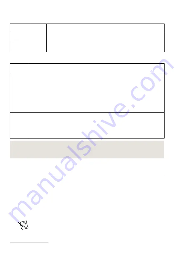
Table 2.
NI 5695 Front Panel LED Indicators
LED
Indications
ACCESS Indicates the basic hardware status of the NI RF signal conditioning module.
OFF—The module is not yet functional, or has detected a problem with a PXI
power rail.
AMBER—The module is being accessed.
GREEN—The module is ready to be programmed.
ACTIVE Indicates the operational status of the NI RF signal conditioning module.
OFF—The module is in an uninitialized state.
GREEN—The module is in a ready state or in use.
Related Information
Configuring the NI 5695 in MAX
Use Measurement & Automation Explorer (MAX) to configure your National Instruments
hardware. MAX informs other programs about which devices reside in the system and how
they are configured. MAX is automatically installed with the NI-5690 instrument driver.
1.
Launch Measurement & Automation Explorer (MAX).
MAX should automatically detect the device you installed.
2.
In the Configuration pane, double-click
Devices and Interfaces
to see the list of installed
devices. Installed devices appear under the name of their associated chassis.
Note
If you are using the NI 5695 with the LabVIEW Real-Time Module,
expand
Remote Systems
. Find your target IP address or name, expand it, and
then expand
Devices and Interfaces
.
1
Refer to the
NI PXI-5695 Specifications
for detailed attenuation specifications.
NI PXI-5695 Getting Started Guide
|
© National Instruments
|
9


