background image

© 

National Instruments Corporation

21

NI SIgnal Generators Getting Started Guide

NI PXI/PCI-5401

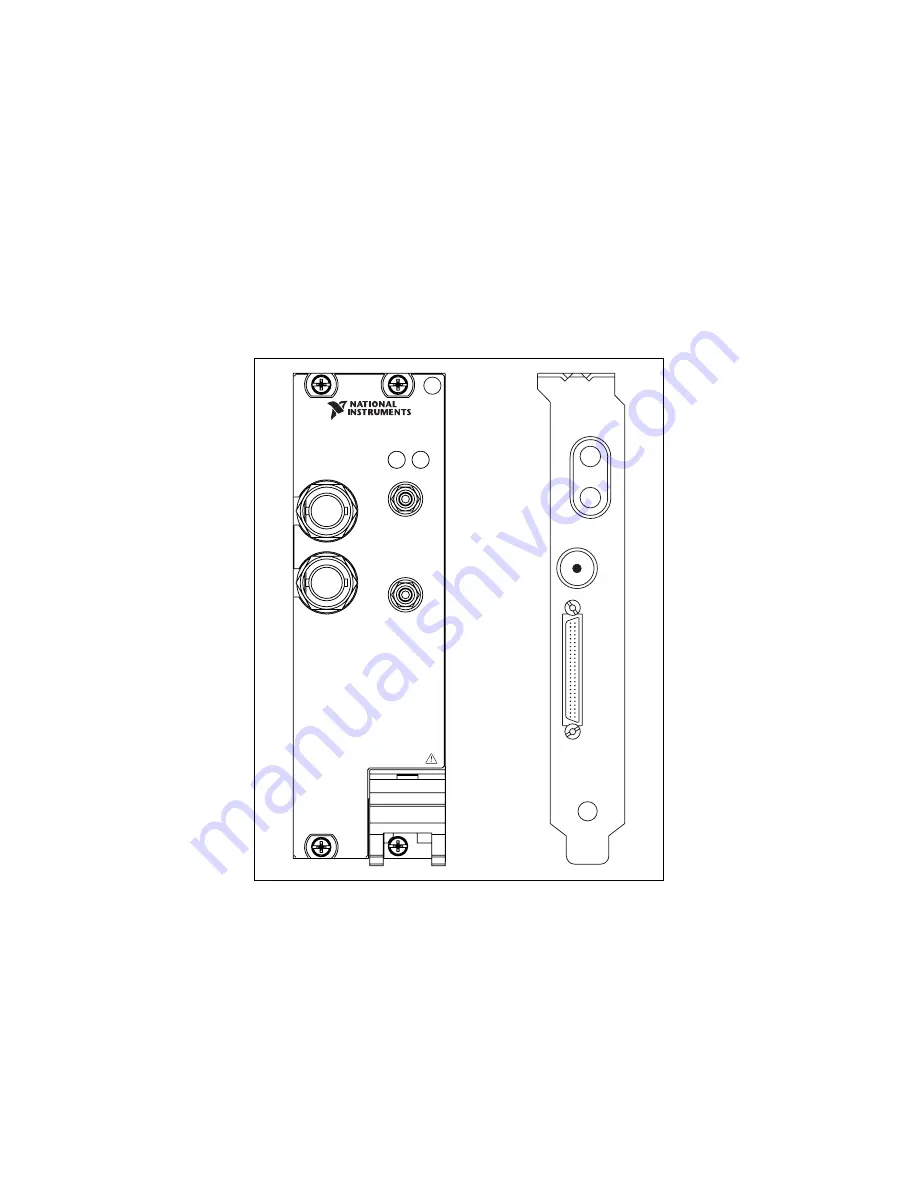
The NI 5401 is a 16 MHz function generator for the PXI platform. 
The NI PXI-5401 has four connectors—two BNC connectors and two SMB 
connectors, as shown in Figure 7. Signal descriptions for the NI PXI-5404 
are listed in Table 1. The NI PCI-5401 has four connectors—three SMB 
connectors and one 50-pin digital connector, as shown in Figure 7. Signal 
descriptions for the NI PCI-5401 are listed in Table 2.

Figure 7.  

NI PXI/PCI-5401 Front Panel

ARB OUT

SYNC OUT

EXT TRIG

PLL REF

LOCK ACCESS

NI PXI-5401

Arbitrary Function Generator

SYNC

PLL IN

ARB

P

A

TTERN OUT

Summary of Contents for PXI-5421

Page 1: ...erutilized and idle equipment along with credit for buybacks and trade ins Custom engineering so your equipment works exactly as you specify Critical and expedited services Leasing Rentals Demos In st...

Page 2: ...e for the NI FGEN instrument driver and information specific to your device For the NI signal generator specifications refer to the specifications document included with each device For free downloads...

Page 3: ...30 NI PXIe 5442 32 Where to Go for Support 34 Conventions The following conventions are used in this manual The symbol leads you through nested menu items and dialog box options to a final action The...

Page 4: ...for disk drives paths directories functions filenames and extensions monospace italic Italic text in this font denotes text that is a placeholder for a word or value that you must supply Platform Text...

Page 5: ...install a damaged device into your computer Store the device in the antistatic envelope when not in use 3 Verifying the Kit Contents The following items are included in the NI signal generator kit NI...

Page 6: ...XI Express chassis and chassis documentation A PXI Express controller or a MXI Express bridge For PCI devices A desktop computer with its documentation Note If your application uses NI TClk synchroniz...

Page 7: ...the Hardware Caution You must power off and unplug the computer or chassis before installing the device To prevent damage to the device caused by ESD or contamination handle the device using the edges...

Page 8: ...e has cooled to an acceptable operating temperature and has been reset successfully Installing PXI Modules To install the device in either a PXI chassis a PXI SCXI combination chassis or a PXI Compact...

Page 9: ...8 Plug in the PXI chassis Uninstalling PXI Modules When removing PXI modules from the chassis ensure that you are grounded with a grounding strap or are touching a grounded metal surface To avoid ESD...

Page 10: ...all the module in a PXI Express slot of a PXI Express chassis Refer to the chassis documentation to determine which slots are designated for PXI Express modules Figure 2 PXI Express Module Installatio...

Page 11: ...te the following steps 1 Power off and unplug the PC 2 Remove the PC cover 3 Insert the device into an open PCI slot as shown in Figure 3 Figure 3 PCI Installation Tip To maximize airflow and extend t...

Page 12: ...s for PXI and PCI Devices section for more information 6 Replace the PC cover 7 Plug in the PC 6 Power On Your Computer or PXI Chassis Windows recognizes any newly installed device the first time you...

Page 13: ...x Devices folder Note If you are using a remote RT target expand Remote Systems find and expand your target and then expand Devices and Interfaces NI 5401 5411 5431 Expand Traditional NI DAQ Legacy De...

Page 14: ...and indicates whether the device passed the test When the self test finishes a message indicates either successful verification or that an error occurred Note If the device does not pass the self tes...

Page 15: ...uired for any type of synchronization including NI TClk synchronization involving an NI DAQmx device For information about NI TClk synchronization refer to Programming NI TClk Synchronization Help in...

Page 16: ...Interfaces right click NI DAQmx Devices 3 Select Create New NI DAQmx Device RTSI Cable 4 To add a device to a RTSI cable right click on the RTSI cable name in the Configuration tree and select Add Dev...

Page 17: ...m the drop down listbox Figure 5 Device Configuration Dialog Box 3 Click the Standard Function Mode button show in the following figure 4 Select the frequency amplitude offset and type of waveform tha...

Page 18: ...ect Load Waveform from disk The Select File dialog box opens and displays waveform example files Note You also can download a waveform by selecting File Load New Waveform For the installation location...

Page 19: ...on a bitmap image using the factory settings a Verify that the Device ID is set to the device number previously configured in MAX b Select Load BMP file and compute video data c Click Browse d Double...

Page 20: ...Help NI FGEN Examples The NI FGEN examples demonstrate some of the functionality of the NI signal generators that you can use or integrate into your applications These examples serve as interactive to...

Page 21: ...orms To view or edit existing waveforms you can open and resample data files saved in binary or ASCII file formats Once imported you can view and edit your waveforms You can also create new waveforms...

Page 22: ...SMB connectors as shown in Figure 7 Signal descriptions for the NI PXI 5404 are listed in Table 1 The NI PCI 5401 has four connectors three SMB connectors and one 50 pin digital connector as shown in...

Page 23: ...nal source and can frequency lock the NI PXI 5401 Sample clock timebase to the external Reference clock Table 2 NI PCI 5401 Front Panel Connectors Connector Access Function ARB Output Provides the wav...

Page 24: ...generator The NI 5406 is a 40 MHz bandwidth 16 bit arbitrary function generator These devices have four BNC connectors as shown in Figure 8 Signal descriptions are listed in Table 3 Figure 8 NI PXI P...

Page 25: ...e waveform being generated on CH 0 It can also be configured to accept a trigger from an external source that can start or step through waveform generation or can route signals out from several clock...

Page 26: ...NI PXI 5404 The NI PXI 5404 is a 100 MHz frequency generator The NI PXI 5404 has five SMB connectors as shown in Figure 9 Signal descriptions are listed in Table 4 Figure 9 NI PXI 5404 Front Panel SIN...

Page 27: ...ctor PFI 0 Input Output Accepts either a TTL signal to start waveform generation or provides an output to synchronize or trigger other devices at a certain time within waveform generation REF OUT Outp...

Page 28: ...The NI PXI 5411 5431 has six connectors two BNC connectors three SMB connectors and one 50 pin digital connector as shown in Figure 10 Signal descriptions are listed in Table 5 Figure 10 NI PXI 5411...

Page 29: ...e waveform being generated You can use this signal to synchronize or trigger other devices at a certain time within waveform generation PLL REF Input Accepts a PLL Reference clock from an external sou...

Page 30: ...411 5431 Front Panel Connectors Connector Access Function ARB Output Provides the waveform output SYNC Output Provides a TTL level output of the waveform being generated at the ARB OUT connector PLL I...

Page 31: ...generator The NI 5441 is a 100 MS s 43 MHz 16 bit arbitrary waveform generator with Onboard Signal Processing OSP These devices have up to five connectors four SMB connectors and one 68 pin male VHDC...

Page 32: ...ut Accepts a trigger from an external source that can start or step through waveform generation or can route signals out from several clock event and trigger sources Refer to the NI Signal Generators...

Page 33: ...ss 100 MS s 43 MHz 16 bit arbitrary waveform generator with Onboard Signal Processing OSP The NI 5442 has four SMB connectors as shown in Figure 13 Signal descriptions are listed in Table 8 Figure 13...

Page 34: ...n also be used as a Sample clock source PFI 0 Input Output Accepts a trigger from an external source that can start or step through waveform generation or can route signals out from several clock even...

Page 35: ...es located around the world to help address your support needs For telephone support in the United States create your service request at ni com support and follow the calling instructions or dial 512...

Page 36: ...National Instruments trademarks Other product and company names mentioned herein are trademarks or trade names of their respective companies For patents covering National Instruments products refer t...

Page 37: ...uipment Have surplus equipment taking up shelf space We ll give it a new home Learn more Visit us at artisantg com for more info on price quotes drivers technical specifications manuals and documentat...

Reviews: