Chapter 1
Getting Started
1-4
©
National Instruments Corporation
The PXI-specific signals are located on P2 and are only found on the
signals that are reserved or not used in the CompactPCI 64-bit
specification. Therefore, all modules that meet the requirements of the
CompactPCI 64-bit specification will function in the PXI-1000B.
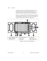
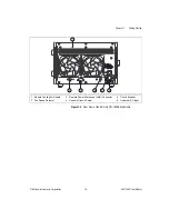
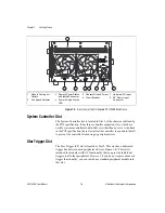
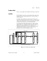
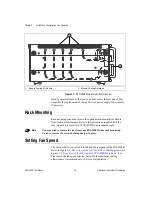
Figures 1-1, 1-2, and 1-3 show some of the key features and components
of the PXI-1000B mainframe. Figure 1-1 shows the front view of the
PXI-1000B. Figure 1-2 shows the rear view of the AC-only chassis, and
Figure 1-3 shows the rear view of the DC-capable chassis.
Figure 1-1.
Front View of the PXI-1000B Mainframe
1
Remote On/Off (Standby) Switch
2
Backplane Connectors
(Located in Slots 1-8)
3
Optional Mounting Brackets
4
Removable Feet
5
Peripheral Slots
6
Star Trigger Slot
7
System Controller Slot
8
Controller Expansion Slots
5
1
2
3
3
7
6
4
8
4
P2
P1


