background image

Chapter 2

Installation and Verification

PCMCIA Serial for Windows 95

2-8

©

 National Instruments Corporation

Connect the Cables

For the PCMCIA serial cards, you can use the standard DB-9 connector 
found on most serial cables.

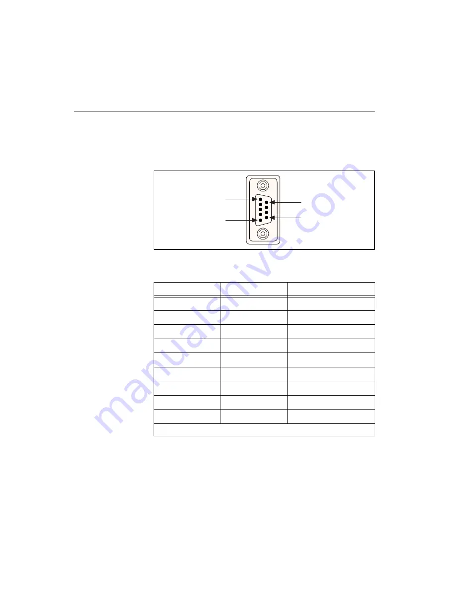
Figure 2-6 and Table 2-1 give the pin locations and descriptions of the 
DB-9 connector, which is found on the PCMCIA serial cable.

Figure 2-6.  

DB-9 Connector Pin Locations

Table 2-1.  

DB-9 Pin Descriptions

DB-9 Pin

232 Signal

485 Signal

Pin 1

DCD

GND

Pin 2

RXD

CTS+ (HSI+)

Pin 3

TXD

RTS+ (HSO+)

Pin 4

DTR

RXD+

Pin 5

GND

RXD-

Pin 6

DSR

CTS- (HSI-)

Pin 7

RTS

RTS- (HSO-)

Pin 8

CTS

TXD+

Pin 9

RI*

TXD-

* This signal is not supported on ports 3 and 4 of the four-port version.

PIN 1

PIN 9

PIN 5

PIN 6

Summary of Contents for PCMCIA Series

Page 1: ...Serial Getting Started with Your PCMCIA Serial Hardware and Software for Windows 95 PCMCIA Serial for Windows 95 December 1997 Edition Part Number 321827A 01 ...

Page 2: ... 3336 Canada Ontario 905 785 0085 Canada Québec 514 694 8521 Denmark 45 76 26 00 Finland 09 725 725 11 France 01 48 14 24 24 Germany 089 741 31 30 Hong Kong 2645 3186 Israel 03 6120092 Italy 02 413091 Japan 03 5472 2970 Korea 02 596 7456 Mexico 5 520 2635 Netherlands 0348 433466 Norway 32 84 84 00 Singapore 2265886 Spain 91 640 0085 Sweden 08 730 49 70 Switzerland 056 200 51 51 Taiwan 02 377 1200 ...

Page 3: ...F PRODUCTS OR INCIDENTAL OR CONSEQUENTIAL DAMAGES EVEN IF ADVISED OF THE POSSIBILITY THEREOF This limitation of the liability of National Instruments will apply regardless of the form of action whether in contract or tort including negligence Any action against National Instruments must be brought within one year after the cause of action accrues National Instruments shall not be liable for any de...

Page 4: ...nications This Class A digital apparatus meets all requirements of the Canadian Interference Causing Equipment Regulations Cet appareil numérique de la classe A respecte toutes les exigences du Règlement sur le matériel brouilleur du Canada Class B Federal Communications Commission This equipment has been tested and found to comply with the limits for a Class B digital device pursuant to part 15 o...

Page 5: ...cables to test this device and provides them for sale to the user The use of inferior or nonshielded interface cables could void the user s authority to operate the equipment under the FCC rules If necessary consult National Instruments or an experienced radio television technician for additional suggestions The following booklet prepared by the FCC may also be helpful Interference to Home Electro...

Page 6: ...nal Programming Tools 1 3 Using the Serial Hardware with Other National Instruments Products 1 4 Chapter 2 Installation and Verification Install the NI Serial Software 2 1 Install the PCMCIA Serial Hardware 2 3 Verify the Installation 2 4 Verify the Hardware Resources 2 6 Determine Which Physical Port Is Associated with COMx 2 7 Run the Diagnostic Test 2 7 Connect the Cables 2 8 Connecting Two Wir...

Page 7: ... 4 3 Setting the Transceiver Mode with DeviceIoControl 4 4 General Programming Requirements 4 5 Setting the Maximum Baud Rate for a 16 Bit Application 4 5 Other Programming Points 4 5 Appendix A Specifications Hardware Specifications A 1 Software Specifications A 2 Appendix B Serial Port Information RS 232 B 1 RS 422 B 1 RS 485 B 2 Serial Communication Issues B 3 Duplex Architectures B 3 Full Dupl...

Page 8: ...g a PCMCIA Serial Card 2 3 Figure 2 4 Device Manager Ports List for PCMCIA Serial Card Correctly Installed 2 5 Figure 2 5 Device Manager Ports List for PCMCIA Serial Card Incorrectly Installed 2 6 Figure 2 6 DB 9 Connector Pin Locations 2 8 Figure 3 1 Port Settings Tab 3 2 Figure 3 2 Advanced Port Settings Dialog Box 3 3 Figure B 1 Typical Full Duplex System B 4 Figure B 2 Typical Half Duplex Syst...

Page 9: ...escriptions 2 8 Table 4 1 Transceiver Control Modes 4 1 Table 4 2 Transceiver Mode Control Bytes 4 3 Table 4 3 DeviceIoControl Function Input Values 4 4 Table A 1 Physical Characteristics of the PCMCIA Serial Cards A 1 Table A 2 Environmental Characteristics of the Serial Hardware A 2 Table A 3 Software Characteristics A 2 Table B 1 RS 232 RS 422 and RS 485 Features B 2 Table D 1 Standard DOS Base...

Page 10: ...l the serial hardware NI Serial software and cables Chapter 3 Configuration contains instructions to help you view or change the communication port settings Chapter 4 Using Your Serial Hardware describes how to set the hardware transceiver control mode for your RS 485 interfaces and lists some general programming requirements Appendix A Specifications describes the characteristics of the serial ha...

Page 11: ...he names of menus menu items parameters dialog boxes dialog box buttons or options icons windows Windows 95 tabs or LEDs bold italic Bold italic text denotes a note italic Italic text denotes variables emphasis a cross reference or an introduction to a key concept This font also denotes text from which you supply the appropriate word or value as in Windows 3 x monospace Text in this font denotes t...

Page 12: ...d Digital Multipoint Systems Microsoft Win32 Software Developer Kit Online Documentation for Win32 Overviews Win32 Reference and Programmer s Guide to Windows 95 Microsoft Corporation NS16550AF Universal Asynchronous Receiver Transmitter with FIFOs National Semiconductor ST16C654 Asynchronous Receiver Transmitter with FIFOs EXAR Corp Customer Communication National Instruments wants to receive you...

Page 13: ...y describes the serial hardware and the NI Serial software How to Use This Manual Yes No Chapter 2 Chapter 3 Write Application Program Passes Gather What You Need to Get Started Chapter 1 Install the NI Serial Software Learn About Transceiver Control Modes Review Programming Requirements Install the Serial Hardware Configure the Serial Port Verify the Installation Connect the Cables Troubleshootin...

Page 14: ...t DB 9 RS 485 termination connector RS 232 9 pin to 9 pin null modem cable RS 232 9 pin to 25 pin null modem cable Serial Hardware Overview The serial hardware gives you a variety of solutions for serial communications The PCMCIA 232 interfaces work with the RS 232 protocols and the PCMCIA 485 interfaces work with the RS 422 and RS 485 protocols You can use the PCMCIA 232 hardware for serial commu...

Page 15: ... Overview The NI Serial software for Windows 95 includes a native Windows device driver that can provide full interrupt driven buffered I O for multiple COM ports Using this driver you can obtain a maximum baud rate of 115 2 KBaud and you can use any number of serial ports under Windows 95 The NI Serial software also provides a configuration utility which is integrated with the Windows 95 Device M...

Page 16: ...ing details LabVIEW is a complete programming environment that departs from the sequential nature of traditional programming languages and features a graphical programming environment It includes all the tools needed for instrument control data acquisition analysis and presentation LabVIEW also includes an extensive instrument driver library For more information about LabWindows CVI and LabVIEW co...

Page 17: ...ables Install the NI Serial Software Before installing the hardware complete the following steps to install the NI Serial software for Windows 95 1 Select Start Settings Control Panel 2 Double click on the Add Remove Programs icon in the Control Panel to launch the Add Remove Programs applet A dialog box similar to the one in Figure 2 1 appears Figure 2 1 Add Remove Programs Properties Dialog Box ...

Page 18: ...he setup wizard guides you through the necessary steps to install the NI Serial software You may go back and change values where appropriate by clicking on the Back You can exit the setup where appropriate by clicking on the Cancel 6 If you need to install your hardware or if this is your first time to install the NI Serial software for Windows 95 skip to the next section Install the PCMCIA Serial...

Page 19: ...to set and you do not need to shut down the system before you insert it Windows 95 automatically displays one or more New Hardware Found dialog boxes when it detects and configures a PC Card If no New Hardware Found box appears follow the steps in Appendix E Forcing Windows 95 to Detect the Serial Hardware Figure 2 3 shows how to insert a PCMCIA serial card and how to connect the cable Figure 2 3 ...

Page 20: ...e is left unconfigured Double click on the System icon in the Control Panel In the System Properties window that appears select the Device Manager tab and click the View devices by type button at the top of the page If necessary double click on the Ports COM LPT icon to view all of the ports The two port and four port PCMCIA cards are configured as devices belonging to the multi function adapters ...

Page 21: ...curred because Windows 95 could not acquire resources for the port or because an interrupt request resource conflict exists If no circled exclamation point appears the serial hardware is installed correctly Figure 2 4 shows an example of NI serial hardware that is installed properly and Figure 2 5 shows an example of NI serial hardware that is not working properly Figure 2 4 Device Manager Ports L...

Page 22: ...erial ports If Windows 95 did not assign any resources to the port the Resources page shows only a Set Configuration Manually button Click on the Set Configuration Manually button and try to assign conflict free resources to your serial hardware For instructions refer to the Selecting Conflict Free Resources section of Appendix D Troubleshooting and Common Questions You may have to free an interru...

Page 23: ...t proceed to the next section Run the Diagnostic Test To verify and test the installation run the diagnostic program that came with your NI Serial software The diagnostic program verifies that your serial driver is installed properly that the configuration of your hardware does not conflict with anything else in your system and that the serial driver can communicate with your hardware correctly To...

Page 24: ... 1 give the pin locations and descriptions of the DB 9 connector which is found on the PCMCIA serial cable Figure 2 6 DB 9 Connector Pin Locations Table 2 1 DB 9 Pin Descriptions DB 9 Pin 232 Signal 485 Signal Pin 1 DCD GND Pin 2 RXD CTS HSI Pin 3 TXD RTS HSO Pin 4 DTR RXD Pin 5 GND RXD Pin 6 DSR CTS HSI Pin 7 RTS RTS HSO Pin 8 CTS TXD Pin 9 RI TXD This signal is not supported on ports 3 and 4 of ...

Page 25: ...85 data acquisition device to a port on your PCMCIA 485 using half duplex communication you need a single twisted pair of wires At the PCMCIA 485 you should connect the TXD and RXD signals pins 8 and 4 on a DB 9 connector pins 5 and 20 on a DB 25 connector together and to one wire You should connect the other end of this wire to both the TXD and RXD signals on the data acquisition device You use t...

Page 26: ...the top of the page 3 Double click the Ports COM LPT icon 4 Double click on the name of the port you want to configure You can now view or change information about your serial port Click on the Resources tab to view information about the hardware resources assigned to the serial port Click on the Port Settings tab to view information about the software configuration for the serial port Refer to th...

Page 27: ...ithout saving changes Communication Port Settings On the Port Settings tab you can change any of the settings by clicking on the arrow button to the right of the setting When you click on the arrow button a list of valid values for that setting appears Select the desired setting from the list Figure 3 1 shows the Port Settings tab Figure 3 1 Port Settings Tab The following sections describe the po...

Page 28: ...dd or no parity bits in each transmitted byte Stop Bits Stop bits is the number of terminating bits on the end of each transmitted serial byte Flow Control Flow control is a method for temporarily halting the stream of serial bytes to prevent overflow Advanced Port Settings You can view or change the advanced port settings by clicking on the Advanced button on the Port Settings tab Figure 3 2 show...

Page 29: ... is available by clicking on the Advanced button on the Port Settings tab FIFO buffers are present on the 16550 compatible UARTs one for the transmitter and one for the receiver Consider the following points when selecting FIFO settings You can select larger FIFO settings to minimize system overhead If transfer rates are high you can lower receive FIFO settings to prevent overrun errors If data si...

Page 30: ...erent bus topologies Table 4 1 lists the status of the transmitters and receivers under each of the transceiver control modes Note Signal names with an overscore such as indicate that the signal is active low Four Wire Mode Use the four wire mode for most full duplex systems In this mode the transmitter and receiver are always enabled This mode is the default Table 4 1 Transceiver Control Modes Mo...

Page 31: ...transmitter Although this mode uses the same method as the with echo mode to control the transmitter the hardware automatically disables the receiver whenever the transmitter is enabled Thus you do not receive packets that you have transmitted Two Wire Mode TXRDY Auto Control In this mode the hardware transparently enables the transmitter and receiver in a two wire system This mode removes the bur...

Page 32: ...ol mode from within a DOS application For each port you want to control write the control byte for the mode you want to select to the scratch register of the UART Table 4 2 shows the control bytes for each mode The scratch register is located at offset 7 from the base address of the port For example if COM2 were located at base address 0x3F8 and you wanted to set the PCMCIA 485 board to two wire m...

Page 33: ... FILE_ANY_ACCESS 2 Use the Win32 function DeviceIoControl Use the defined control code value listed in Step 1 to set the transceiver mode and the input buffer values unsigned long listed in Table 4 3 for programming different transceiver modes For example to set two wire auto control mode use the following call ULONG TranceiverMode 131 DeviceIoControl hDevice IOCTL_SERIAL_SET_TRANSCEIVER_MODE PVOI...

Page 34: ...xff20 You can then use this constant as you would any other baud rate value in your Windows communication calls For example you can place it into a DCB structure and pass it to SetCommState For a Win32 application do not use the constant shown here for 115 200 baud Use the constant defined in the Win32 communications header file provided with your compiler Other Programming Points As you begin dev...

Page 35: ...Table A 1 Physical Characteristics of the PCMCIA Serial Cards Characteristic Specification Dimensions 85 6 cm by 54 0 cm by 5 0 mm 3 370 by 2 126 by 0 197 in I O Connector Special Cable with DB 9 Dsub Connector and 15 Pin Converter for PC Card Power Requirement from PCMCIA expansion slot PCMCIA 232 PCMCIA 485 PCMCIA 232 2 PCMCIA 485 2 PCMCIA 232 4 5 VDC 40 mA Typical 5 VDC 100 mA Typical 5 VDC 60 ...

Page 36: ...t Component Temperature Relative Humidity 0 to 40 C 10 to 90 noncondensing Storage Environment Temperature Relative Humidity 20 to 70 C 5 to 90 noncondensing EMI FCC Class A Verified Table A 3 Software Characteristics Characteristic Specification Maximum Serial Transfer Rate 115 200 bps Space Required for NI Serial Software 1 MB Actual speed may vary considerably from speed shown due to system and...

Page 37: ...ften increase the actual performance of the bus past the limitations on speed and distance recommended in the specification RS 422 RS 422 as specified in the EIA RS 422 A Standard Electrical Characteristics of Balanced Voltage Digital Interface Circuits defines a serial interface much like RS 232 However RS 422 uses balanced or differential transmission lines Balanced transmission lines use two tr...

Page 38: ... same line RS 485 defines the electrical characteristics necessary to ensure adequate signal voltages under maximum load short circuit protection and the ability to withstand multiple drivers driving conflicting signals at the same time Table B 1 lists the features of the RS 232 RS 422 and RS 485 standards Table B 1 RS 232 RS 422 and RS 485 Features Feature RS 232 RS 422 RS 485 Type of transmissio...

Page 39: ...ctions at the same time First one device transmits over the wire s to the receiver of the second device When the first device finishes transmitting both devices switch the connections from their transmitter to their receiver or vice versa The device that was receiving data can then transmit over the line In full duplex communication the devices use a separate wire or pair of wires for simultaneous...

Page 40: ...nsmitters to the bus master s receiver Because in a differential system each transmission line is composed of two separate wires a full duplex system is often referred to as a four wire system Figure B 1 shows a typical full duplex system Figure B 1 Typical Full Duplex System Half Duplex A typical half duplex multidrop bus architecture also involves a master slave protocol In a half duplex system ...

Page 41: ...mbedded terminating resistors for easy termination Figure B 3 shows a multidrop network using terminating resistors Figure B 3 Multidrop Network Using Terminating Resistors DTE vs DCE Data Terminal Equipment DTE and Data Communications Equipment DCE were the terms used in the RS 232 specification for the types of equipment on either end of a serial connection A DCE is called Data Circuit Terminati...

Page 42: ...to the other transmitter and one receiver is connected to the other receiver In this setup no transmissions can occur Thus these applications must use a cabling scheme that connects the transmitter on one device to the receiver on the other device and vice versa This method is known as null modem cabling because it replaces the two modems that traditional RS 232 applications would require between ...

Page 43: ...re Information Before physically removing the serial hardware from the computer you must remove the hardware information from the Windows 95 Device Manager Follow these steps to uninstall the hardware 1 Double click the System icon under Start Settings Control Panel The System Properties dialog box appears 2 Select the Device Manager tab 3 Click the View devices by type button 4 Double click on th...

Page 44: ... C 1 Figure C 1 Selecting an Interface to Uninstall 6 Click the Remove button Note To remove ports on two port and four port PCMCIA cards from within the Device Manager you must open the Multi function adapters class select the name of your interface and click on the Remove button 7 In the Confirm Device Removal dialog box click on the OK button to remove this interface or click on Cancel to cance...

Page 45: ...escribed in the previous section You do not need to shut down Windows 95 before uninstalling the software Complete the following steps to remove the NI Serial software 1 Select Start Settings Control Panel 2 Double click on the Add Remove Programs icon in the Control Panel to launch the Add Remove Programs applet A dialog box similar to the one in Figure C 2 appears This dialog box lists the softw...

Page 46: ...Add Remove button The uninstall program runs and removes all folders programs VxDs DLLs and registry entries associated with the NI Serial software Figure C 3 shows the results of a successful uninstallation 4 Remove your PCMCIA card from your computer Figure C 3 Uninstallation Results If you want to reinstall the hardware and software refer to Chapter 2 Installation and Verification ...

Page 47: ...View Resources tab 6 Select the Interrupt Request IRQ button By scanning through the list of interrupt request settings you can determine which devices are using which interrupt request levels 7 When you have located a device which you are not currently using click Cancel to exit the Computer Properties window 8 Double click on the icon for the device in the Device Manager list of devices In the D...

Page 48: ...e Multi function adapters class and double click on the name of your interface Use the Resources page to change the resources Any resource changes are automatically reflected to the child devices 6 Uncheck the Use automatic settings checkbox and click on the Change Setting button If the system does not allow you to change settings select the configuration that gives you a conflict free base I O ad...

Page 49: ...pt test failed error message appears verify the hardware resources as described in Chapter 2 Installation and Verification If the test still fails you probably have an interrupt level conflict with legacy boards Refer to the next section Resolving Resource Conflicts with Legacy Boards Resolving Resource Conflicts with Legacy Boards Resource conflicts typically occur when your system contains legac...

Page 50: ...ses in Table D 1 to a National Instruments serial port Windows 95 automatically changes the COM port name to the corresponding one listed in this table You do not need to change the IRQ setting for this name change to occur To change the base address refer to the Selecting Conflict Free Resources section earlier in this appendix How do I change the resources assigned to PCMCIA two port or four por...

Page 51: ...nager Figure D 1 Multi Function Adapter Class in the Device Manager How do I remove information about PCMCIA two port or four port serial cards from the Device Manager Because the two port PCMCIA cards are single physical devices that support multiple ports they are registered as multi function adapters in the Device Manager Each port is a child device listed under Ports COM LPT Windows 95 does no...

Page 52: ...file gives the version of the software To read the file select Read Me under Start Programs NI Serial Software for Windows 95 What information should I have before I call National Instruments When you call National Instruments you should have the results of the Diagnostic test Also make sure you have filled out the hardware and software configuration form in Appendix F Customer Communication ...

Page 53: ... the New Hardware Found dialog box To correct the problem complete the following steps 1 Select Start Settings Control Panel 2 Double click on the System icon 3 Select the Device Manager page 4 Click the View devices by type button 5 Double click on the Ports COM LPT icon to display a list of all ports that Windows 95 recognizes If you have previously installed a PCMCIA serial card double click on...

Page 54: ...example COM 5 COM 6 COM 7 or COM 8 Figure E 1 shows the Ports list in the Device Manager with a port selected Figure E 1 Port Selected in Device Manager 7 Click the Remove button and click on OK to confirm the removal of the serial hardware information 8 Repeat steps 6 and 7 until all serial port entries are removed Then click on Refresh to force Windows 95 to detect serial hardware and display th...

Page 55: ...ms does not answer your questions we offer fax and telephone support through our technical support centers which are staffed by applications engineers Electronic Services Bulletin Board Support National Instruments has BBS and FTP sites dedicated for 24 hour support with a collection of files and documents to answer most common customer questions From these sites you can also download the latest i...

Page 56: ...ents office in your country contact the source from which you purchased your software to obtain support Country Telephone Fax Australia 03 9879 5166 03 9879 6277 Austria 0662 45 79 90 0 0662 45 79 90 19 Belgium 02 757 00 20 02 757 03 11 Brazil 011 288 3336 011 288 8528 Canada Ontario 905 785 0085 905 785 0086 Canada Quebec 514 694 8521 514 694 4399 Denmark 45 76 26 00 45 76 26 02 Finland 09 725 72...

Page 57: ...____ Instruments used _________________________________________________________________ _______________________________________________________________________________ National Instruments hardware product model _____________ Revision ____________________ Configuration ___________________________________________________________________ National Instruments software product ___________________ Vers...

Page 58: ...__________ COM3 ________________ _________________ COM4 ________________ _________________ COM5 ________________ _________________ COM6 ________________ _________________ COM7 ________________ _________________ COM8 ________________ _________________ COM9 ________________ _________________ Other Products Computer make and model ________________________________________________________ Microprocesso...

Page 59: ..._____________________________________ _______________________________________________________________________________ _______________________________________________________________________________ _______________________________________________________________________________ _______________________________________________________________________________ __________________________________________...

Page 60: ...cond C Celsius COM Computer Output Microform DB xx subminiature D connector where xx is the number of pins DCE Data Communications Equipment or Data Circuit Terminating Equipment DMA direct memory access DTE Data Terminal Equipment Data Terminal Ready where the overscore denotes that the signal is active low EIA Electronic Industries Association EMI electromagnetic interference FCC Federal Communi...

Page 61: ...nches I O input output IRQ interrupt request ISA Industry Standard Architecture m meters MB megabytes of memory PC personal computer RAM random access memory RX Receive s seconds TX Transmit Transmit Ready where the overscore denotes that the signal is active low UART universal asynchronous receiver transmitter V volts VDC volts direct current TXRDY ...

Reviews: