Chapter 3
Signal Connections
©
National Instruments
3-11
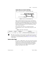
Counter Source to Counter Out Delay
Fig
u
re 3-5 shows the Ctr
n
So
u
rce to Ctr
n
InternalO
u
tp
u
t delay.
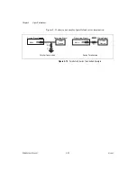
Figure 3-5.
CtrnSource to CtrnInternalOutput Delay
Fig
u
re 3-5 shows the delay between the active edge of the Ctr
n
So
u
rce
signal and the active edge of the Ctr
n
InternalO
u
tp
u
t signal. In the fig
u
re,
the Ctr
n
So
u
rce and Ctr
n
InternalO
u
tp
u
t signals are active high. If yo
u
u
se
the p
u
lse o
u
tp
u
t mode for the Ctr
n
InternalO
u
tp
u
t signal, yo
u
will see the
TC p
u
lse one Ctr
n
So
u
rce period before the Ctr
n
InternalO
u
tp
u
t toggles
u
nder the toggle o
u
tp
u
t mode.
The o
u
tp
u
t delay listed in Table 3-5 is for internal signals. The
corresponding delay val
u
es at a connector block are larger d
u
e to cable
delays.
Note
When
u
sing d
u
plicate co
u
nt prevention mode, the minim
u
m period of signal
u
sed
as the so
u
rce of the co
u
nter m
u
st be greater than or eq
u
al to fo
u
r times the period of the
maxim
u
m timebase. For more information, refer to the
of this doc
u
ment.
Counter
n
Gate Signal
Yo
u
can select any PFI or RTSI, as well as many other internal signals like
the Co
u
nter
n
Gate (Ctr
n
Gate) signal. The Ctr
n
Gate signal is config
u
red in
edge-detection or level-detection mode depending on the application
performed by the co
u
nter. The gate signal can perform many different
operations incl
u
ding starting and stopping the co
u
nter, generating
interr
u
pts, and saving the co
u
nter contents.
Table 3-5.
Output Delay for Internal Signals
Parameter
Typical
Maximum
Description
Tso
16 ns
26 ns
Ctr
n
So
u
rce to Ctr
n
InternalO
u
tp
u
t delay
Ctr
n
InternalOutput
Tso
Tso
Ctr
n
Source
Summary of Contents for PCI-6601
Page 1: ...PCI 6601...

