Chapter 3
Signal Connections
©
National Instruments
3-3
are t
fltrclk
or shorter. A p
u
lse with a width between these two ranges may or
may not pass, depending on the phase of the p
u
lse with respect to the filter
clock timebase.
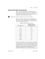
Table 3-1 s
u
mmarizes the properties of the different filter settings.
Yo
u
individ
u
ally config
u
re the filter setting for each PFI line. The filters are
u
sef
u
l to maintain signal integrity. They can prevent meas
u
rement errors
ca
u
sed by noise, crosstalk, or transmission line effects.
Note
The digital filters on the NI 660
x
devices are not enabled by defa
u
lt.
For more information abo
u
t
u
sing the digital filters on yo
u
r device, refer to
the
NI-DAQmx Help
.
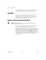
Power-On State
The PFI lines are weakly p
u
lled down within the NI-TIO ASIC, and the
RTSI lines are weakly p
u
lled high. Connections for p
u
lling
u
p the PFI lines
or for stronger p
u
ll-down connections m
u
st be made external to the
NI 660
x
. These connections affect the drive strength of NI 660
x
devices
when the lines p
u
lled
u
p or down are
u
sed as o
u
tp
u
ts.
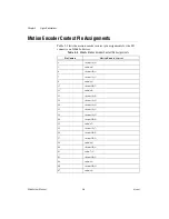
I/O Connector Pinout
Fig
u
re 3-2 shows the pino
u
t of the NI 6601. Fig
u
re 3-3 shows the pino
u
t of
the NI 6602/6608. The descriptions beside each pin are in the following
format: Signal Name / DIO Context / Co
u
nter Context (Defa
u
lt).
Table 3-1.
Filter Settings
Filter Setting
Pulse Width Passed
Pulse Width Blocked
5
μ
s
5
μ
s
2.5
μ
s
1
μ
s
1
μ
s
500 ns
500 ns
500 ns
250 ns
100 ns
100 ns
50 ns
Programmable setting
with period of clock = t
fltrclk
2*t
fltrclk
t
fltrclk
Summary of Contents for PCI-6601
Page 1: ...PCI 6601...


