


NI-XNET CAN HS/FD Transceiver Cable Instructions
|
© National Instruments
|
7
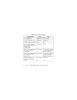
the reference ground for CAN_H and CAN_L. You can connect the
CAN bus reference ground (sometimes referred to as CAN_V) to
one or both COM pins.
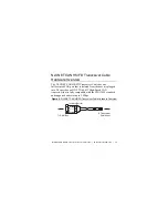
The D-Sub connector shell connects through the NI-XNET CAN
HS/FD Transceiver Cable shielding to the connector on the host
port end. The shielding does not electrically connect to the COM
signals.
The NI-XNET CAN HS/FD Transceiver Cable gets power from
the XNET host port. No external power from the CAN bus is
required.
Note
The NI-XNET CAN HS/FD Transceiver Cable is
internally powered, but LIN and some other cables may
require external power when the bus standard requires it.
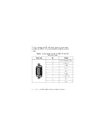
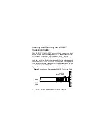
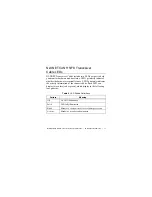
The NI-XNET CAN HS/FD Transceiver Cable pinout is listed in
Table 1.
The NI-XNET CAN HS/FD Transceiver Cable features
software-selectable bus termination for High-Speed CAN
transceivers. On the NI-XNET CAN HS/FD Transceiver Cable,
you can enable 120
Ω
termination resistors between CAN_H and


