background image

Chapter 1

NI Smart Camera Overview

©

 National Instruments Corporation

1-3

NI 17xx Smart Camera User Manual

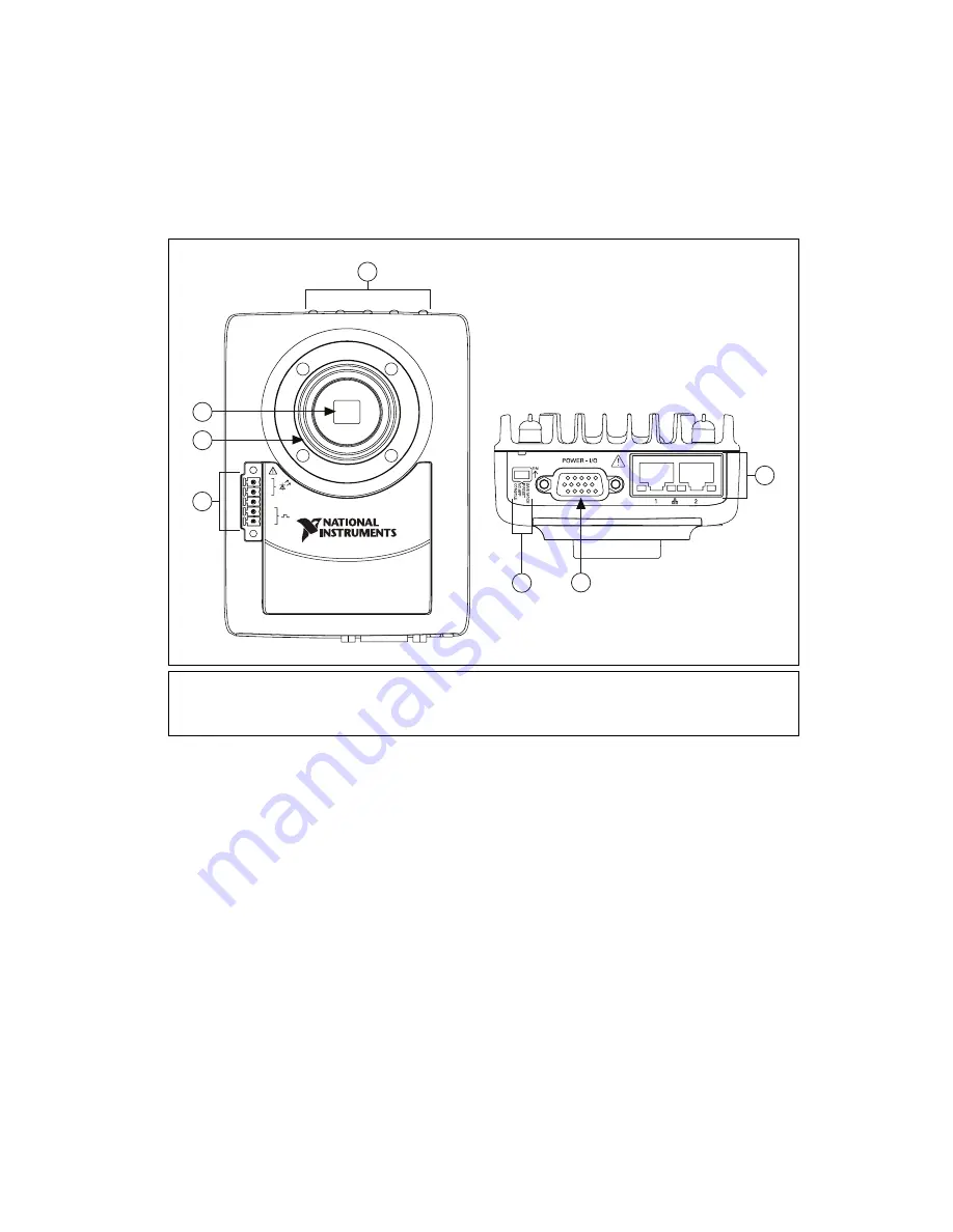
Figure 1-1 shows the smart camera.

Figure 1-1.  

NI Smart Camera

1

Image Sensor

2

Standard C Lens Mount

3

Lighting Connector

4

LEDs

5

DIP Switches

6

POWER-I/O Connector

7

Ethernet Ports

GND

+

-

5V

24V

6

1

2

3

4

7

NI 17XX SMART CAMERA

Summary of Contents for NI Vision NI 17 Series

Page 1: ...NI Vision NI 17xx Smart Camera User Manual NI 17xx Smart Camera User Manual June 2008 372429B 01 ...

Page 2: ...Lebanon 961 0 1 33 28 28 Malaysia 1800 887710 Mexico 01 800 010 0793 Netherlands 31 0 348 433 466 New Zealand 0800 553 322 Norway 47 0 66 90 76 60 Poland 48 22 3390150 Portugal 351 210 311 210 Russia 7 495 783 6851 Singapore 1800 226 5886 Slovenia 386 3 425 42 00 South Africa 27 0 11 805 8197 Spain 34 91 640 0085 Sweden 46 0 8 587 895 00 Switzerland 41 56 2005151 Taiwan 886 02 2377 2222 Thailand 6...

Page 3: ...cluding photocopying recording storing in an information retrieval system or translating in whole or in part without the prior written consent of National Instruments Corporation National Instruments respects the intellectual property of others and we ask our users to do the same NI software is protected by copyright and other intellectual property laws Where NI software may be used to reproduce s...

Page 4: ...nt of Communications DOC Changes or modifications not expressly approved by NI could void the user s authority to operate the equipment under the FCC Rules Class A Federal Communications Commission This equipment has been tested and found to comply with the limits for a Class A digital device pursuant to part 15 of the FCC Rules These limits are designed to provide reasonable protection against ha...

Page 5: ...NI Vision Builder for Automated Inspection 1 4 LabVIEW 1 5 LabVIEW Real Time Module 1 5 NI Vision Development Module 1 5 NI Vision Acquisition Software 1 6 Chapter 2 Power and I O POWER I O Connector 2 1 NI Smart Camera Power Requirements 2 2 Isolated Inputs 2 3 Isolated Outputs 2 4 Protecting Against Inductive Loads 2 6 Connecting to Serial Devices 2 6 Communicating with the Console 2 6 Connectin...

Page 6: ...e 5 1 Acquiring Images 5 2 Internal Timing 5 2 External Trigger 5 3 Maximum Frame Rate 5 6 Determining the Maximum Frame Rate 5 7 Determining the Scan Mode 5 7 Determining the Exposure Time 5 8 Determining the Lighting Mode 5 8 Determining the Trigger Delay 5 9 Calculating the Minimum Frame Period 5 9 Chapter 6 LEDs and DIP Switches Understanding the LED Indicators 6 1 Device Initialization 6 2 PO...

Page 7: ...D 7 2 DHCP and Static IP Address Assignment 7 3 Firewall Considerations 7 4 Subnet Considerations 7 4 Chapter 8 Thermal Considerations and Mounting Thermal Considerations 8 1 Mounting the NI Smart Camera 8 2 Appendix A Specifications Appendix B Troubleshooting Appendix C Maintenance Appendix D Technical Support and Professional Services Glossary Index ...

Page 8: ...oduct refer to Getting Started with the NI 17xx Smart Camera for information about precautions to take When symbol is marked on a product it denotes a warning advising you to take precautions to avoid electrical shock bold Bold text denotes items that you must select or click in the software such as menu items and dialog box options Bold text also denotes parameter names italic Italic text denotes...

Page 9: ...ments in the NI Developer Zone Using the NI 17xx Smart Camera Direct Drive Lighting Controller Demonstrates how to utilize the Direct Drive lighting controller feature on the NI 17xx Smart Camera with LabVIEW or Vision Builder for Automated Inspection A Practical Guide to Machine Vision Lighting Explains machine vision lighting concepts and theories NI Vision Builder for Automated Inspection Docum...

Page 10: ...on Concepts Manual Describes the basic concepts of image analysis image processing and machine vision This document also contains in depth discussions about imaging functions for advanced users NI Vision for LabVIEW Help Describes how to create machine vision and image processing applications in LabVIEW using the Vision Development Module The help file guides you through tasks beginning with setti...

Page 11: ... incorporate an image sensor processor and digital I O in a compact rugged housing Table 1 1 shows the differentiating features for each smart camera model Table 1 1 NI Smart Camera Models NI Smart Camera Model Processor Image Sensor Direct Drive Lighting Controller Quadrature Encoder Support NI 1722 400 MHz PowerPC 1 3 inch Sony ICX424AL CCD Monochrome 640 480 pixels VGA No No NI 1742 533 MHz Pow...

Page 12: ...ller is an integrated controller to directly power a variety of third party current controlled lights Refer to Chapter 4 Lighting for more information about the Direct Drive lighting controller The smart camera also has one 5 V TTL strobe output and one unregulated 24 V strobe output for lighting control The smart camera also includes LEDs for communicating system status four DIP switches to speci...

Page 13: ...on 1 3 NI 17xx Smart Camera User Manual Figure 1 1 shows the smart camera Figure 1 1 NI Smart Camera 1 Image Sensor 2 Standard C Lens Mount 3 Lighting Connector 4 LEDs 5 DIP Switches 6 POWER I O Connector 7 Ethernet Ports GND 5V 24V 6 1 2 3 4 5 7 NI 17XX SMART CAMERA ...

Page 14: ...Development Module are sold separately NI Vision Builder for Automated Inspection Vision Builder for Automated Inspection Vision Builder AI is configurable machine vision software you can use to configure the NI Smart Camera and prototype benchmark and deploy machine vision applications Creating applications in Vision Builder AI does not require programming Vision Builder AI allows you to easily c...

Page 15: ...ns VIs without a user interface and offers a stable platform for real time VIs For more information about the LabVIEW Real Time Module refer to the LabVIEW Help NI Vision Development Module The NI Vision Development Module is an image acquisition processing and analysis library of hundreds of functions for the following common machine vision tasks Pattern matching Particle analysis Gauging Taking ...

Page 16: ...also controls the I O and image acquisition on the smart camera NI IMAQ includes an extensive library of VIs you can call from LabVIEW These VIs include routines for video configuration continuous and single shot image acquisition and trigger control The NI IMAQ driver software performs all functions necessary for acquiring and saving images but does not perform image analysis NI IMAQ features bot...

Page 17: ...or the POWER I O connector The two pins used to connect to a power supply pin 15 and pin 5 are also shown in the table Refer to Getting Started with the NI 17xx Smart Camera for information about connecting a power supply to the NI Smart Camera Table 2 1 lists the signal names and pin numbers for the 15 pin POWER I O connector The table also lists the wire colors for the 15 pin D SUB pigtail cable...

Page 18: ...g strobe is an unregulated output dependent on the range of the power supply provided to the smart camera If the power provided to the smart camera is 20 15 with 5 AC ripple the external lighting strobe output could be as high as 30 V If the provided power exceeds the input voltage specifications of the third party lighting controller do not connect the 24 V lighting strobe output to the controlle...

Page 19: ...mage the NI Smart Camera Caution The isolated inputs and outputs on the smart camera provide an easy means for preventing ground loops that could degrade signal integrity The isolation on the smart camera is not safety isolation You can wire an isolated input to both sourcing and sinking output devices Refer to Figures 2 1 and 2 2 for wiring examples by output type Refer to Appendix A Specificatio...

Page 20: ... with any external power supply greater than 30 VDC Voltages greater than 30 VDC may damage the NI Smart Camera Caution The isolated inputs and outputs on the smart camera provide an easy means for preventing ground loops that could degrade signal integrity The isolation on the smart camera is not safety isolation Sensor Power Sensor Common NI 17xx NPN Sinking Output Device TrigIn IsoIn 0 IsoIn 1 ...

Page 21: ... used to drive external loads as shown in Figures 2 3 and 2 4 Figure 2 3 Connecting an Isolated Output to a Sourcing External Load Figure 2 4 Connecting an Isolated Output to a Sinking External Load Sourcing Load IsoOut IsoOut NI 17xx Sensor Power Sensor Common IsoOut IsoOut NI 17xx Sensor Power Sensor Common Sinking Load ...

Page 22: ...ect the RS232_TXD signal on the smart camera to the Rx signal on your serial device Connect COM on the smart camera to the ground of your serial device When the CONSOLE DIP switch is in the OFF position you can use the NI Serial driver for serial communication You must install the NI Serial software on the smart camera it is not installed by default Refer to the Serial Hardware and Software Help f...

Page 23: ... specify your trigger delay in terms of positional units such as inches or centimeters after applying the resolution information of your encoder rather than time National Instruments does not recommend the use of single ended encoders with the smart camera This configuration would require the ground for a single ended encoder to be connected to the COM pin of the smart camera and the PhaseA and Ph...

Page 24: ... Connecting Differential Line Drivers Figure 2 6 shows the internal quadrature encoder RS 422 input circuit Figure 2 6 NI Smart Camera Quadrature Encoder Input Circuit Phase A Phase A Phase A Phase A Phase B Phase B Phase B Phase B Encoder NI 17xx Twisted Pair Twisted Pair Phase A Phase A Phase B Phase B 3 3 V 10 kΩ 10 kΩ 10 kΩ 10 kΩ 7 5 kΩ 7 5 kΩ 7 5 kΩ 7 5 kΩ NI 17xx ...

Page 25: ...ur system includes the object you want to inspect To calculate the horizontal and vertical field of view FOV of your imaging system use Equation 3 1 and the specifications for the image sensor of your smart camera as listed in Appendix A Specifications 3 1 where FOV is the field of view in either the horizontal or vertical direction Pixel Pitch measures the distance between the centers of adjacent...

Page 26: ...can mode is 3 2 Similarly the field of view in the vertical direction is 3 3 Based on the result of Equations 3 2 and or 3 3 you can see that you might need to adjust the various parameters in the FOV equation until you achieve the right combination of components that match your inspection needs This might include increasing your working distance choosing a lens with a shorter focal length or chan...

Page 27: ...of light from the scene Refer to Appendix A Specifications to find the normalized spectral response curves for the VGA and SXGA sensors Partial Scan Mode Partial scan mode is a method of obtaining higher frame rates by reading out only a portion of the image from the sensor Partial scan is frequently used when an application requires higher speed but less resolution than the sensor offers in full ...

Page 28: ...ical direction The NI Smart Camera supports 1 2 binning Figure 3 3 illustrates what happens to the sensor output during binning Figure 3 3 Binning Gain Gain is a multiplier applied to the analog signal prior to digitization Increasing the gain increases the amplitude of the signal Gain allows you to trade off between making smaller signals more visible at the cost of increased noise and no longer ...

Page 29: ... in the brightest areas of the image Gain can be useful when there is not enough available light and you need to increase the brightness of your images However increasing gain multiplies both the signal and noise When possible it is preferable to add additional lighting Hardware Binarization The NI Smart Camera supports binarization and inverse binarization of acquired images Binarization and inve...

Page 30: ...he background region are set to the image white value Figure 3 5 illustrates binarization and inverse binarization Figure 3 5 Binarization and Inverse Binarization You can enable hardware binarization in the following ways In Vision Builder AI configure the Lookup Table attribute on the Advanced tab of the Acquire Image Smart Camera step Refer to the NI Vision Builder for Automated Inspection Conf...

Page 31: ...NI Smart Camera to control a light Lighting Connector Figure 4 1 shows the lighting connector on the NI Smart Camera Caution All signals on the lighting connector are outputs from the smart camera Do not connect any external voltage or current source to any pin on the lighting connector Note The NI 1722 does not offer the Direct Drive lighting controller Do not connect to the LED and LED connector...

Page 32: ...ve controller can operate in continuous or strobed mode When operating in strobed mode the controller can provide more current to the light than in continuous mode The average power dissipated while strobing the light for a short period of time at a higher current can be comparable to the average power dissipated while running the light continuously at a lower current Table 4 1 shows the maximum a...

Page 33: ... Direct Drive lighting controller in strobed mode care must be taken to ensure that the resulting strobe duty cycle and strobe duration do not violate the limits of the Direct Drive lighting controller or the limits of the light For your convenience the software calculates the resulting strobe duration and duty cycle for your configured frame rate and exposure time It then compares them to the lim...

Page 34: ... support regarding this lighting data file or the light to which it refers Not Digitally Signed The information contained within the lighting file meets the requirements of Direct Drive lighting however it has not been verified that the information is safe to use with the specified light Use this file at your own risk Invalid The information contained within the lighting file is unusable because t...

Page 35: ...nly to the following NI Smart Cameras National Instruments software provides support for a variety of lights from major machine vision lighting companies However if your light is not in the list of supported lights you may still be able to use your light with the Direct Drive lighting controller To determine if your light is compatible with the NI Smart Camera verify the following The light is cur...

Page 36: ... the smart camera Note The voltage drop of a light can vary significantly with environmental conditions such as ambient temperature current supplied and strobe time Refer to Appendix A Specifications for complete specifications for the Direct Drive lighting controller Connecting a Light to the Direct Drive Lighting Controller This section applies only to the following NI Smart Cameras Figure 4 2 i...

Page 37: ... The 24 V strobe output is nominally a 24 V output if 24 V power is supplied to the smart camera Caution The 24 V external lighting strobe is an unregulated output dependent on the range of the power supply provided to the smart camera If the power provided to the smart camera is 20 15 with 5 AC ripple the output could be as high as 30 V If the provided power exceeds the input voltage specificatio...

Page 38: ...abVIEW configure the 24V Strobe and 5V Strobe lighting properties Refer to the NI IMAQ VI Reference Help for more information about configuring the 5 V TTL and 24 V strobe outputs In MAX select the 5 V TTL Strobe and or 24 V Strobe checkboxes on the Lighting tab of the smart camera configuration page Refer to the Measurement Automation Explorer Help for NI IMAQ for more information about configuri...

Page 39: ...r Manual Figure 4 4 illustrates how to connect an external lighting controller to the 24 V output on the NI Smart Camera Figure 4 4 Connecting an External Lighting Controller to the 24 V Strobe Output 24 V Strobe Output 18 V 30 V GND Output External Lighting Controller NI 17xx LED ...

Page 40: ...t of a time relative to the amount of light in the environment results in a dark low contrast image Exposing the image sensor for too long of a time relative to the amount of light in the environment results in a bright low contrast image When the image sensor is exposed for an appropriate amount of time relative to the light in the environment acquired images will exhibit appropriate contrast to ...

Page 41: ...ample in a building with windows the ambient light can vary significantly with weather Also standard fluorescent lighting flickers at a rate that is perceivable by the smart camera In these situations the ambient light must be overridden with a dedicated light source to ensure reproducible results Acquiring Images You can configure the NI Smart Camera to acquire images based on internal timing or ...

Page 42: ...tion of a signal generated by a proximity sensor You can trigger the smart camera at rates up the maximum frame rate Refer to the Maximum Frame Rate section for information about factors that affect the maximum frame rate To use an external trigger the trigger signal must be provided on the TrigIn IsoIn 0 and TrigIn IsoIn 0 inputs to the camera and triggering must be enabled in the software Refer ...

Page 43: ...rnal trigger configured to use the rising edge as the active edge The time between the active edge of the trigger and the assertion of the lighting strobe is a user configurable trigger delay The trigger delay can be configured in either milliseconds or quadrature encoder counts The NI 1722 does not support quadrature encoders 1 User Configurable Trigger Delay 2 Lighting Turn On Time 3 Beginning o...

Page 44: ... the part is positioned in front of the smart camera regardless of changes in speed of the conveyor belt For other applications a delay specified in milliseconds is sufficient If you are strobing a light there is a short delay while the lighting controller turns on the light This delay is represented by the lighting turn on time in Figure 5 1 Table 5 2 lists the lighting turn on times After the li...

Page 45: ...eriod is the time from the start of exposure on one frame to the start of exposure on the next frame as shown in Figure 5 2 Figure 5 2 Frame Period The frame period is affected by the following factors Partial scan mode as described in the Partial Scan Mode section of Chapter 3 NI Smart Camera Image Sensor Binning mode as described in the Binning section of Chapter 3 NI Smart Camera Image Sensor E...

Page 46: ...ng the Scan Mode section and min frame period is the minimum amount of time for the strobe and trigger mode as described in the Calculating the Minimum Frame Period section Determining the Scan Mode The maximum frame rate for selected scan mode is determined by the partial scan mode and binning mode Because the amount of data read out of the sensor is less in 1 2 or 1 4 scan mode the readout takes...

Page 47: ...l strobe outputs of the smart camera the smart camera can expose one image while it is reading out the previous image allowing for the highest possible frame rates Figure 5 3 illustrates this relationship The smart camera receives the trigger for the second image while it is still reading out the first image The first image readout finishes before the second image readout begins Figure 5 3 Image A...

Page 48: ...imum frame period the trigger delay value further limits the min frame period When the trigger delay is specified in milliseconds the software includes this in the calculation of the maximum frame rate indicator Calculating the Minimum Frame Period Refer to Equations 5 3 and 5 4 to calculate the minimum frame period for untriggered acquisitions with and without strobing 5 3 5 4 1 Image Readout Com...

Page 49: ...n Tables 5 1 and 5 2 list the values for the trigger synchronization variability and the lighting turn on time respectively The image readout duration varies depending on the smart camera configuration as shown in Table 5 3 Table 5 3 Image Readout Duration Smart Camera Model Full Scan 1 2 Scan 1 4 Scan Binning NI 1722 NI 1742 NI 1762 16 38 ms 8 86 ms 5 49 ms 8 17 ms NI 1744 NI 1764 76 47 ms 41 38 ...

Page 50: ...s This chapter provides information about the location and functionality of the LED indicators and DIP switches on the NI Smart Camera Understanding the LED Indicators Figure 6 1 shows the location of the LEDs on the NI Smart Camera Figure 6 1 NI Smart Camera LEDs FAIL PASS IMG ACQ STATUS POWER ...

Page 51: ...receive an IP address within 60 seconds the device automatically restarts and tries again The smart camera attempts to acquire an IP address from a DHCP server three times If after the third time the smart camera has not been assigned an IP address the smart camera reverts to the unconfigured state and the IP address resets to 0 0 0 0 The STATUS LED flashes to indicate that the smart camera is in ...

Page 52: ... with the NI 17xx Smart Camera for information about installing software on the smart camera 3 Flashes Green The smart camera is in safe mode because the SAFE MODE DIP switch is in the ON position Refer to the Configuring DIP Switches section for information about the SAFE MODE DIP switch 4 Flashes Green The smart camera has experienced two consecutive software exceptions The smart camera automati...

Page 53: ...at is user configurable through the IMAQ property node in LabVIEW or the Read Write I O step in Vision Builder AI FAIL LED The FAIL LED is a red LED that is user configurable through the IMAQ property node in LabVIEW or the Read Write I O step in Vision Builder AI If the IMG ACQ LED and the FAIL LED both flash red it indicates that the NI Smart Camera has shut down because the maximum internal tem...

Page 54: ...ATUS LED flashes green three times when the smart camera is in safe mode Keep the SAFE MODE switch in the OFF position during normal operation IP RESET Switch To clear the NI Smart Camera IP settings move the IP RESET switch to the ON position and reapply power or restart the smart camera Use the IP RESET switch to reset the TCP IP settings when moving the camera from one subnet to another or when...

Page 55: ...he NO APP switch in the OFF position during normal operation CONSOLE Switch With a serial port terminal program you can use the CONSOLE switch to read device information from the NI Smart Camera during startup such as the IP address and firmware version When the CONSOLE switch is in the ON position the serial port outputs device information and is not available for applications The smart camera re...

Page 56: ...ary port The primary port can be configured to acquire an IP address from a DHCP server The secondary port can only be configured for a static IP address Both Ethernet ports of the smart camera can connect to a 10 100 or 1 000 Mbps 1 Gbps Ethernet network at either full or half duplex The smart camera automatically detects the speed and duplex capabilities of its link partner and configures for th...

Page 57: ...ernet cable The LED is unlit when no cable is connected or if the smart camera or the device connected at the other end of the cable are powered down The LED is solid green when a link is established but there is no traffic activity on the link The LED will flash green when there is traffic activity on the link If the smart camera is connected to a corporate network traffic that is not related to ...

Page 58: ... smart camera Also the DHCP server does not allow other devices to use the IP address that is already assigned to your smart camera Although using a DHCP server makes configuring an IP address easy configuring a static IP address can be more reliable Consider the following potential issues before using a DHCP server to assign an IP address to the smart camera If the network has both static IP addr...

Page 59: ...ost computer The first time you configure the smart camera you must also install software on it After configuring the smart camera use DHCP to assign an IP address or reassign a static IP address for the subnet where you want the smart camera to reside then physically move the smart camera to the other subnet Refer to Getting Started with the NI 17xx Smart Camera for more information about configu...

Page 60: ...era Thermal Considerations The NI Smart Camera can operate in environments with ambient temperatures ranging from 0 to 45 C The maximum housing temperature of the smart camera is 65 C Refer to Appendix A Specifications for complete specifications Figure 8 1 shows the location to take temperature measurements on the smart camera Figure 8 1 Measuring the NI Smart Camera Housing Temperature 1 Region ...

Page 61: ... reads 70 C or more the smart camera immediately halts operation and becomes unresponsive The IMG ACQ LED and the FAIL LED flash red You must remove and reapply power to the smart camera to recover from this condition To maximize the cooling efficiency of the smart camera mount it to a thermally conductive structure as specified in the Mounting the NI Smart Camera section Mounting the NI Smart Cam...

Page 62: ...ings necessary to create a custom mount for the smart camera Figure 8 2 Back View of the NI Smart Camera with Dimensions Figure 8 3 Front View of the NI Smart Camera with Dimensions 85 80 mm 3 378 in 60 58 mm 2 385 in 47 00 mm 1 850 in 95 75 mm 3 770 in 23 50 mm 0 925 in Optical Axis 24 25 mm 0 955 in Optical Axis 30 89 mm 1 216 in 32 80 mm 1 291 in 38 91 mm 1 532 in ...

Page 63: ...ide View of the NI Smart Camera with Dimensions Figure 8 5 Bottom View of the NI Smart Camera with Dimensions 50 62 mm 1 993 in 44 14 mm 1 738 in 117 66 mm 4 632 in 33 12 mm 1 304 in 24 78 mm 0 975 in 21 41 mm 0 843 in 25 45 mm 1 002 in 27 86 mm 1 097 in 20 71 mm 0 815 in 13 84 mm 0 545 in Optical Axis ...

Page 64: ... 20 15 IEC 1311 450 mA NI 1742 1744 1762 1764 Direct Drive disabled 24 VDC 20 15 IEC 1311 450 mA Direct Drive enabled 24 VDC 20 15 IEC 1311 800 mA Reverse polarity protection Yes Memory SDRAM 128 MB Nonvolatile program data memory 128 MB Image data storage Unlimited using FTP or an Ethernet hard drive Processor NI 1722 Freescale PowerQUICC II Pro 400 MHz NI 1742 1744 Freescale PowerQUICC II Pro 53...

Page 65: ...scan 7 4 μm horizontal 7 4 μm vertical Binning 1 2 7 4 μm horizontal 14 8 μm vertical Maximum frame rate1 Full scan Up to 60 fps 1 2 scan Up to 109 fps 1 4 scan Up to 175 fps Binning 1 2 Up to 114 fps Optical format 1 3 in Sensor readout Progressive scan Bits per pixel 8 bits 256 gray levels Minimum exposure time 36 28 μs Exposure time increment 31 2 μs 1 Refer to the Maximum Frame Rate section of...

Page 66: ...GA Sensor NI 1744 1764 Only Sensor Sony CCD ICX205AL Active pixels SXGA Full scan 1 280 1 024 1 2 scan 1 280 512 1 4 scan 1 280 256 Binning 1 2 1 280 512 Pixel size 4 65 μm 4 65 μm Pixel pitch Full scan 1 2 scan 1 4 scan 4 65 μm horizontal 4 65 μm vertical Binning 1 2 4 65 μm horizontal 9 3 μm vertical 0 9 0 8 0 7 0 6 0 5 0 4 0 3 0 2 0 1 0 1 0 400 500 600 700 900 800 1000 Wavelength nm Relative Re...

Page 67: ...8 bits 256 gray levels Minimum exposure time 76 68 μs Exposure time increment 71 6 μs Spectral characteristics Refer to Figure A 2 Figure A 2 SXGA Sensor Spectral Response Curve Gamma 1 0 fixed 1 Refer to the Maximum Frame Rate section of Chapter 5 Image Acquisition for more information about calculating the maximum frame rate for your application 0 9 0 8 0 7 0 6 0 5 0 4 0 3 0 2 0 1 0 1 0 400 500 ...

Page 68: ...ower supply Minimum voltage drop across LED LED terminals 7 V Strobe frequency Operating frame rate Maximum strobe duty cycle 45 5 V external strobe Polarity Programmable Strobe frequency Operating frame rate VOH minimum 3 8 V VOL maximum 0 55 V IOH maximum 12 mA IOL maximum 12 mA 24 V external strobe Polarity Active high Strobe frequency Operating frame rate ON state Voltage Unregulated output dr...

Page 69: ... Default baud rate 9 600 bps Hardware flow control No Optically Isolated Inputs and Outputs Isolated Inputs Channels 2 Input type Sinking sourcing both inputs must have the same configuration Digital logic levels OFF state Input current 0 mA to 0 1 mA Input voltage 0 V to 1 V ON state Input current 3 mA to 5 4 mA Input voltage 20 V to 30 V Minimum pulse width 1 ms Isolated Outputs Channels 2 Outpu...

Page 70: ...11 77 cm 8 58 cm 5 06 cm 4 63 in 3 38 in 1 99 in Weight 525 g 18 52 oz Environmental The NI Smart Camera is intended for indoor use only Operating temperature Ambient temperature 0 to 45 C Maximum camera housing temperature 65 C Humidity 10 to 90 RH noncondensing IP rating 40 Pollution degree 2 Operating shock IEC 60068 2 27 50 g 3 ms half sine 18 shocks at 6 orientations 30 g 11 ms half sine 18 s...

Page 71: ...rical equipment for measurement control and laboratory use EN 61326 EMC requirements Minimum Immunity EN 55011 Emissions Group 1 Class A CE C Tick ICES and FCC Part 15 Emissions Class A Note For full EMC compliance operate this device with shielded cabling CE Compliance The NI Smart Camera meets the essential requirements of applicable European Directives as amended for CE marking as follows 2006 ...

Page 72: ...i com environment This page contains the environmental regulations and directives with which NI complies as well as other environmental information not included in this document Waste Electrical and Electronic Equipment WEEE EU Customers At the end of their life cycle all products must be sent to a WEEE recycling center For more information about WEEE recycling centers and National Instruments WEE...

Page 73: ...apter 7 Ethernet Ports for more information Another device on the network is using the IP address assigned to the smart camera This can happen when you assign the same static IP to two devices you assign a static IP that is in the range of the IP address available for DHCP use on your network or the DHCP server assigns the same IP address to another device Either remove or reconfigure the other de...

Page 74: ...gured state the smart camera has an IP address of 0 0 0 0 and only limited software loads In the unconfigured state the smart camera has network connectivity If the smart camera is on the same subnet as the host computer then refreshing the list of remote devices in MAX or Vision Builder AI will cause the smart camera to appear with an IP address of 0 0 0 0 Use MAX or Vision Builder AI to reconfig...

Page 75: ... to bring the voltage drop within the specified range of the smart camera Refer to Appendix A Specifications for more information The smart camera ran out of memory The reason may be that acquired images are still in memory When developing applications with LabVIEW use the IMAQ Dispose VI to destroy an image and free the space it occupied in memory This VI is required for each image created in an ...

Page 76: ...rity LED pin to the anode and LED pin to cathode You have properly configured the maximum light settings in MAX or Vision Builder AI For safety reasons the default configuration of the smart camera does not enable lighting until you configure the maximum lighting current settings that are appropriate for your light You have enabled the Direct Drive lighting controller in MAX or Vision Builder AI T...

Page 77: ...fications for more information The voltage drop of the light may have exceeded the maximum voltage or minimum voltage requirements of the smart camera The voltage drop of a light can vary significantly with environmental conditions such as temperature current and strobe time Verify that the voltage drop across the LED and LED terminals is within the specified range of the smart camera Your light m...

Page 78: ...lect the appropriate strobe from the External Strobe Generation control Triggering Problems No Trigger is Received If you are not receiving a trigger verify the following The trigger is wired to the TrigIn IsoIn 0 and TrigIn IsoIn 0 signals If TrigIn IsoIn 0 and IsoIn 1 are both being used that the devices they are connected to are either both sinking NPN or both sourcing PNP The trigger is connec...

Page 79: ... LED does not light up check that the power supply is 24 V 20 15 and within the specifications outlined in Appendix A Specifications Verify that the power supply can supply enough current for the smart camera model in use Using a power supply that is not within these specifications might result in an unresponsive or unstable system and could damage the smart camera Caution The 24 V external lighti...

Page 80: ...r from dust and dirt Avoid drastic temperature changes to prevent dew condensation When necessary use the following procedure to clean the sensor at a workstation equipped with anti ESD facilities If dust sticks to the CCD first attempt to blow it off from the side of the sensor using ionized air If oils are present on the sensor clean the sensor with a cotton bud and ethyl alcohol Be careful not ...

Page 81: ...dard Service Program Membership This program entitles members to direct access to NI Applications Engineers via phone and email for one to one technical support as well as exclusive access to on demand training modules via the Services Resource Center NI offers complementary membership for a full year after purchase after which you may renew to continue your benefits For information about other te...

Page 82: ...ic compatibility EMC and product safety You can obtain the DoC for your product by visiting ni com certification If you searched ni com and could not find the answers you need contact your local office or NI corporate headquarters Phone numbers for our worldwide offices are listed at the front of this manual You also can visit the Worldwide Offices section of ni com niglobal to access the branch o...

Page 83: ... or 255 and the background has a pixel intensity of 0 C CCD Charge Coupled Device A chip that converts light into electronic signals D DIP switch Dual Inline Package switch Direct Drive lighting controller A lighting controller integrated into some models of the National Instruments smart camera that can directly power current controlled lights E Ethernet cable standard CAT 5 CAT 5e or CAT 6 Ether...

Page 84: ...e ratio of output to input I IEC International Electrotechnical Commission A standard setting body IEEE Institute of Electrical and Electronics Engineers A standard setting body I O Input output The transfer of data to from a computer system involving communications channels operator interface devices or data acquisition and control interfaces L LED Light emitting diode M MAC Media access control ...

Page 85: ...rom each other The phase difference indicates the position and direction of rotation R rising edge The digital signal transition from the low state to the high state RS 232 Standard electrical interface for serial data communications S sensor resolution The number of columns and rows of CCD pixels in the camera sensor sensor size The size of the active area of an image sensor subnet A set of syste...

Page 86: ...er Any event that causes or starts some form of data capture V VDC Volts direct current VGA sensor Video Graphics Array sensor Image sensor that features a resolution of 640 480 pixels VI Virtual Instrument A combination of hardware and or software elements typically used with a PC that has the functionality of a classic stand alone instrument W working distance The distance from the front of the ...

Page 87: ... 5 sinking output sensors to isolated inputs 2 4 sourcing output sensors to isolated inputs 2 3 to a quadrature encoder 2 7 to serial devices 2 6 CONSOLE DIP switch 6 6 conventions used in the manual ix D Declaration of Conformity NI resources D 2 detailed specifications A 1 device initialization 6 2 diagnostic tools NI resources D 1 DIP switches 6 1 Direct Drive 4 2 connecting a light 4 6 lightin...

Page 88: ...onnector 4 1 controller 4 2 files 4 4 turn on time 5 5 LUT lookup table See hardware binarization N National Instruments support and services D 1 NI 17xx acquiring images 5 2 assigning an IP address 7 3 binning 3 4 communicating with the console 2 6 connecting an external lighting controller 4 7 an isolated output to a sinking external load 2 5 an isolated output to a sourcing external load 2 5 si...

Page 89: ... PASS LED 6 4 power 2 1 requirements 2 2 POWER LED 6 2 POWER I O connector 2 1 pin descriptions 2 1 programming examples NI resources D 1 protecting against inductive loads 2 6 Q quadrature encoder 2 7 using a quadrature encoder to delay a trigger 5 5 R related documentation x hardware documents x LabVIEW documents xi NI Vision Acquisition Software documents xi NI Vision Builder for Automated Insp...

Page 90: ...D error indications B 7 lighting problems B 4 network problems B 1 NI resources D 1 run time problems B 3 triggering problems B 6 U understanding LED indicators 6 1 V VGA sensor 3 1 Vision Acquisition Software 1 6 Vision Builder for Automated Inspection 1 4 Vision Development Module 1 5 description 1 5 W Web resources D 1 ...

Reviews: