NI PXIe-5653 Calibration Procedure
|
© National Instruments
|
9
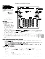
Verifying LO1 Frequency Accuracy
This verification ensures that the internal local oscillator (LO) circuitry is adjusted for correct
frequency accuracy. Complete the following procedure to determine the as-found status of the
NI 5653.
1.
Connect the NI 5653 LO1 front panel connector to the signal source analyzer RF IN front
panel connector.
2.
Connect the signal source analyzer REF IN rear panel connector to the rubidium frequency
reference output connector.
3.
Create a new device session for the NI 5653.
4.
Create a list of test frequencies from 3.2 GHz to 8.3 GHz in 100 MHz increments including
endpoints.
5.
Set the RF frequency to the first value of the frequency array you created in step 4 and
commit the settings to hardware.
6.
Check the signal generation status and verify that there are no reported errors or warnings.
7.
Configure the signal source analyzer as follows:
•
Center frequency: Frequency from the list in step 4
•
Reference level: 20 dBm
•
Frequency span: 1 kHz
•
Reference clock source: External
8.
Measure the frequency of the peak that is returned by the signal source analyzer at
approximately the corresponding point in the frequency array you created in step 4.
9.
Use the following formula to calculate the deviation:
10. Repeat steps 5 through 9 for each subsequent point in the frequency array created in step 4.
11. Ensure that the results in step 8 are less than the result of the following formula:
Initial Accuracy
+
Aging +
Temperature Stability
Where
Initial Accuracy
=
Aging
=
Temperature Stability
=
12. Close the device session.
Δ
f
f
measured
MHz
(
)
f
ected
exp
MHz
(
)
–
f
ected
exp
MHz
(
)
------------------------------------------------------------------------------------
=
50 10
9
–
×
100 10
9
–
×
Year
--------------------------
NumberofYearsSinceLastAdjustment
×
10 10
9
–
×