National Instruments NI ISM-7401 User Manual Download Page 12

12

|

ni.com

|

NI ISM-7401/7402 User Manual

Using the Optional Encoder

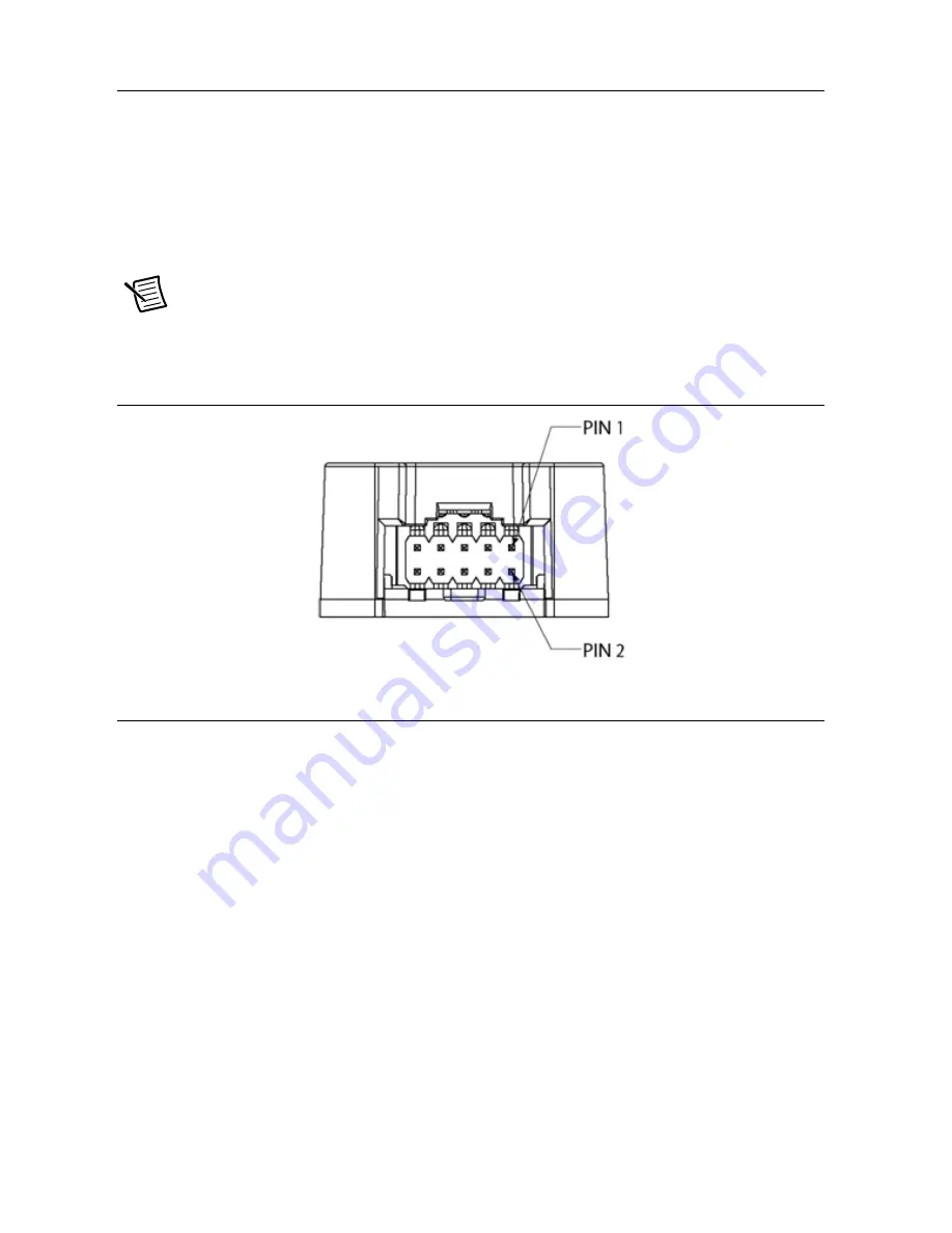
There are three versions of the NI ISM-7401 and NI ISM-7402: the NI ISM-7401/7402 has a 
single shaft, the ISM-7401D/7402D has a dual shaft, and the ISM-7401E/7402E has a dual shaft 
with a 1000-line, incremental encoder assembled to the rear shaft of the unit. You can connect 
the A, B, and Index (Z) channel signals of this encoder to the external controller for position 
verification and enhanced performance, depending on the features of the controller. To facilitate 
connecting the encoder signals to your external controller, you should purchase cable part 
number 748995-01.

Note

If you are making your own cable to connect the encoder signals to your 

controller, NI recommends using a shielded cable with four or five twisted pairs for 
improved noise immunity.

Figure 16.  

NI ISM-7401/7402 Encoder Connector

Configuring the NI ISM-7401/7402

Setting the Current

Set the current to 100% to achieve maximum torque. However, under some conditions you 
might want to reduce the current to save power or lower motor temperature. This is important if 
the motor is not mounted to a surface that will help it conduct heat away or if you expect the 
ambient temperature to be high.

Step motors produce torque in direct proportion to current, but the amount of heat generated is 
roughly proportional to the square of the current. If you operate the motor at 90% of rated 
current, the motor provides 90% of the rated torque and approximately 81% as much heat. At 
70% current, the torque is reduced to 70% and the heating to about 50%.

Summary of Contents for NI ISM-7401

Page 1: ...onnection Examples STEP DIR 9 Connection Examples EN 9 Connecting the Digital Output 10 Using the Optional Encoder 12 Configuring the NI ISM 7401 7402 12 Setting the Current 12 Setting Idle Current 13...

Page 2: ...nto the connector Source of step signals such as a PLC or motion controller Refer to Choosing a Power Supply for more information AMPLIFIER 12 60 VDC from external power supply Status LEDs Step Pulse...

Page 3: ...efer to the Heating section for more information Caution Never use your NI ISM 7401 7402 in a space where there is no airflow or where other devices cause the surrounding air to be higher than 40 C Ca...

Page 4: ...everse the wires Reverse connection will damage your drive and void your warranty When you rapidly decelerate a load from a high speed much of the kinetic energy of that load transfers back to the pow...

Page 5: ...National Instruments 5 Current The following charts list the maximum current required for each motor at several common power supply voltages Note Full load curves are abbreviated because of the speed...

Page 6: ...6 ni com NI ISM 7401 7402 User Manual...

Page 7: ...nergy of that load is transferred back to the power supply This can trip the overvoltage protection of a switching power supply causing it to shut down Unregulated power supplies are better suited for...

Page 8: ...o 24 V logic DIR High speed digital input for the direction signal 5 V to 24 V logic EN 5 V to 24 V input for commanding the removal of power from the motor Note To convert STEP and DIR inputs to STEP...

Page 9: ...Outputs Figure 7 Connecting to Indexer with Sinking Outputs Figure 8 Connecting to Indexer with Differential Outputs Connection Examples EN Connecting the Enable input as shown in Figure 9 causes the...

Page 10: ...When the proximity sensor activates the input closes Connecting the Digital Output The NI ISM 7401 7402 has a digital output labeled OUT This output closes to signal a fault condition Figure 12 Intern...

Page 11: ...ments 11 Diagrams of each type of connection follow Caution Do not connect the output to more than 30 VDC The current through the output terminal must not exceed 80 mA Figure 13 Sinking Output Figure...

Page 12: ...t the encoder signals to your controller NI recommends using a shielded cable with four or five twisted pairs for improved noise immunity Figure 16 NI ISM 7401 7402 Encoder Connector Configuring the N...

Page 13: ...5 Some applications such as those supporting a vertical load require a high holding torque In such cases set the idle current to 90 as shown in the following figure Figure 18 Configuring Idle Current...

Page 14: ...eration and deceleration Smaller step sizes result in smoother motion and more precise speed but also require a higher step pulse frequency to achieve maximum speed The smallest step size is 1 25 600t...

Page 15: ...uses a command filter which causes a slight delay or lag in the motion The following figure shows an example of the delay that can occur from using the step smoothing filter Figure 22 Delay Due to Fil...

Page 16: ...of steps per revolution in combination with high motor speeds you may be commanding the drive at step rates above 150 kHz In such cases you should set switch 5 to the OFF position as shown below Figur...

Page 17: ...nts 17 Figure 25 Configuring Self Test on Switch 4 Reference Materials Torque Speed Curves Figure 26 Torque Curve for NI ISM 7401 ISM 7401Torque at 5A phase 12V 24V 48V 120 140 80 100 120 oz in 40 60...

Page 18: ...7402 at commonly used power supply voltages Refer to these curves when planning your application Use the charts depicting typical power dissipation when planning the thermal design of your applicatio...

Page 19: ...NI ISM 7401 7402 User Manual National Instruments 19 Maximum Duty Cycle Figure 28 Duty Cycle for the ISM 7401 Figure 29 Duty Cycle for the ISM 7402...

Page 20: ...com NI ISM 7401 7402 User Manual Temperature Figure 30 Temperature vs Speed for the NI ISM 7401 Figure 31 Temperature vs Speed for the NI ISM 7402 ISM 7401 Temperature vs Speed ISM 7402 Temperature vs...

Page 21: ...ational Instruments 21 Power Consumption Figure 32 Power Consumption for the NI ISM 7401 Figure 33 Power Consumption for the NI ISM 7402 5 0A phase Full Load ISM 7401 Power Consumption 5A phase Full L...

Page 22: ...02 User Manual Power Dissipation Figure 34 Power Dissipation for the NI ISM 7401 Figure 35 Power Dissipation for the NI ISM 7402 5 0A phase Full Load ISM 7401 Power Dissipation 5 0A phase Full Load IS...

Page 23: ...NI ISM 7401 7402 User Manual National Instruments 23 Mechanical Outlines Figure 36 Mechanical Outline for the NI ISM 7401 Top View Side View Front View Rear View...

Page 24: ...24 ni com NI ISM 7401 7402 User Manual Figure 37 Mechanical Outline for the NI ISM 7401D Top View Side View Front View Rear View...

Page 25: ...NI ISM 7401 7402 User Manual National Instruments 25 Figure 38 Mechanical Outline for the NI ISM 7401E Top View Side View Front View Rear View...

Page 26: ...26 ni com NI ISM 7401 7402 User Manual Figure 39 Mechanical Outline for the NI ISM 7402 Top View Side View Front View Rear View...

Page 27: ...NI ISM 7401 7402 User Manual National Instruments 27 Figure 40 Mechanical Outline for the NI ISM 7402D Top View Side View Front View Rear View...

Page 28: ...tions Amplifier Digital MOSFET 16 kHz PWM Protection Over voltage under voltage over current over temperature Supply voltage 12 VDC to 60 VDC Under voltage alarm 10 VDC Over voltage shutdown 75 VDC Ov...

Page 29: ...kHz setting 0 25 s at 2 MHz setting Fault Output Photodarlington 80 mA 30 VDC max Voltage drop 1 2 V max at 80 mA Physical NI ISM 7401 Size 2 22 in 3 35 in 3 35 in 56 4 mm 85 mm 85 mm not including pi...

Page 30: ...neration clamp NI SMD 7700 NI part number 748908 01 Power Supply NI PS 12 24 VDC 6 3 A NI part number 748906 01 NI PS 13 48VDC 6 7A NI part number 748907 01 Alarm Codes In the event of a drive fault o...

Page 31: ...cted data rights as set forth in FAR 52 227 14 DFAR 252 227 7014 and DFAR 252 227 7015 Worldwide Support and Services The NI website is your complete resource for technical support At ni com support y...

Reviews: