
1-26
|
ni.com
Chapter 1
Getting Started with the cDAQ Chassis
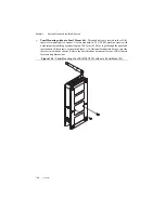
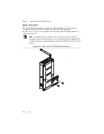
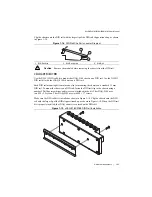
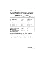
Caution
Remove the module(s) before removing the chassis from the DIN rail.
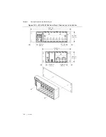
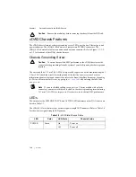
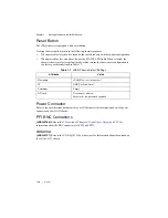
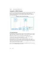
cDAQ Chassis Features
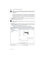
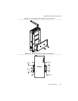
The cDAQ chassis features a chassis grounding screw, LEDs, reset button, Ethernet port, and
power connector. The cDAQ-9188 chassis also features two PFI BNC connectors. The
cDAQ-9191 chassis also features an antenna and antenna connector. Refer to Figure 1-1, 1-2,
or 1-3 for locations of the cDAQ chassis features.
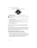
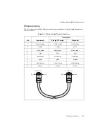
Chassis Grounding Screw
Caution
To ensure the specified EMC performance, the cDAQ chassis
must
be
connected to the grounding electrode system of your facility using the chassis ground
terminal.
The wire should be 1.31 mm
2
(16 AWG) or larger solid copper wire with a maximum length of
1.5 m (5 ft). Attach the wire to the earth ground of the facility’s power system. For more
information about earth ground connections, refer to the KnowledgeBase document,
Grounding
for Test and Measurement Devices
, by going to
and entering the Info Code
emcground
.
Note
If you use shielded cabling to connect to a C Series module with a plastic
connector, you must attach the cable shield to the chassis grounding terminal using
1.31 mm
2
(16 AWG) or larger wire. Use shorter wire for better EMC performance.
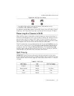
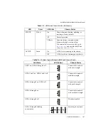
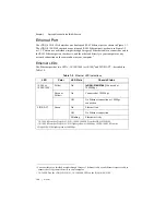
LEDs
The statuses for the POWER, STATUS, and ACTIVE LED indicators on the cDAQ chassis are
listed in Table 1-3.
The cDAQ-9191 also features four wireless signal strength LED indicators. Refer to Table 1-4
for the wireless signal strength LED patterns.
Table 1-3.
LED State/Chassis Status
LED
Color
LED State
Chassis Status
POWER
Green
On
Power on
Off
Power off


