OPERATING INSTRUCTIONS AND SPECIFICATIONS
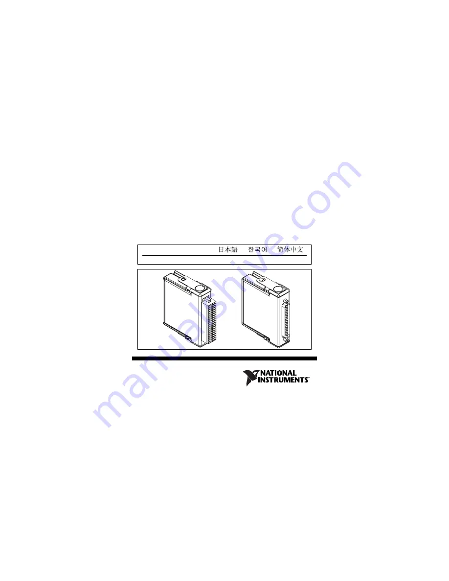
NI 9205
32-Channel,
±
200 mV to
10 V, 16-Bit Analog Input
Module
ni.com/manuals
Deutsch
Français
Page 1: ...OPERATING INSTRUCTIONS AND SPECIFICATIONS NI 9205 32 Channel 200 mV to 10 V 16 Bit Analog Input Module ni com manuals Deutsch Français ...
Page 2: ...ling configuring and programming the system refer to the system documentation Visit ni com info and enter cseriesdoc for information about C Series documentation Note The safety guidelines and specifications in this document are specific to the NI 9205 The other components in the system might not meet the same safety ratings and specifications Refer to the documentation for each component in the s...
Page 3: ...dous voltages to the NI 9205 with DSUB If hazardous voltages are connected to the module take the following precautions A hazardous voltage is a voltage greater than 42 4 Vpk or 60 VDC to earth ground Caution Ensure that hazardous voltage wiring is performed only by qualified personnel adhering to local electrical standards Caution Do not mix hazardous voltage circuits and human accessible circuit...
Page 4: ... You must use the NI 9940 connector backshell kit to ensure that the terminals are not accessible Figure 1 shows the NI 9940 connector backshell Note You can use the NI 9940 connector backshell only with the NI 9205 with spring terminal Figure 1 NI 9940 Connector Backshell Safety Guidelines for Hazardous Locations The NI 9205 is suitable for use in Class I Division 2 Groups A B C D T4 hazardous lo...
Page 5: ...nnect I O side wires or connectors unless power has been switched off or the area is known to be nonhazardous Caution Do not remove modules unless power has been switched off or the area is known to be nonhazardous Caution Substitution of components may impair suitability for Class I Division 2 Caution For Zone 2 applications install the system in an enclosure rated to at least IP 54 as defined by...
Page 6: ...nA IIC T4 or Ex nL IIC T4 equipment Special Conditions for Marine Applications Some modules are Lloyd s Register LR Type Approved for marine applications To verify Lloyd s Register certification visit ni com certification and search for the LR certificate or look for the Lloyd s Register mark on the module Caution To meet radio frequency emission requirements for marine applications use shielded c...
Page 7: ... AI26 AI27 AI28 AI29 AI30 AI31 AI0 AI1 AI2 AI3 AI4 AI5 AI6 AI7 DO0 COM AI16 AI17 AI18 AI19 AI20 AI21 AI22 AI23 AISENSE 1 2 3 4 5 6 7 8 9 10 11 12 13 14 15 16 17 18 19 20 21 22 23 24 25 26 27 28 29 30 31 32 33 34 35 36 37 AI0 AI1 AI2 AI3 AI4 AI5 AI6 AI7 AI16 AI17 AI18 AI19 AI20 AI21 AI22 AI23 COM DO0 AI8 AI9 AI10 AI11 AI12 AI13 AI14 AI15 AI24 AI25 AI26 AI27 AI28 AI29 AI30 AI31 AISENSE PFI0 1 2 3 4 ...
Page 8: ... has an AI terminal or pin to which you can connect an analog output device The NI 9205 is capable of an aggregate sampling rate of 250 kS s The NI 9205 also supports triggering Refer to the software help for information about input trigger modes The NI 9205 channels share a common ground that is isolated from the other modules in the system All channels share a programmable gain instrumentation a...
Page 9: ...detachable spring terminal connector Insert the screwdriver into a spring clamp activation slot and press a wire into the corresponding connector terminal then remove the screwdriver to clamp the wire into the terminal Refer to the Specifications section for more information about spring terminal wiring Refer to Figure 4 for an illustration of connecting wires to the NI 9205 with spring terminal A...
Page 10: ...uments recommends that you use a backshell kit or shielded cable to protect the connections For the NI 9205 with spring terminal use the NI 9940 backshell to protect the connections For the NI 9205 with DSUB use a 37 pin shielded cable or the NI 9933 backshell to protect the connections Refer to Figure 1 for an illustration of the NI 9940 connector backshell Refer to Figure 5 for an illustration o...
Page 11: ... signal sources Make sure the devices you connect to the NI 9205 are compatible with the input specifications of the module Refer to the Specifications section for more information about the input specifications When connecting various sources to the NI 9205 you can use differential single ended or a combination of differential and single ended connections Refer to Figures 6 7 and 8 for diagrams o...
Page 12: ...or each measurement thus reducing the number of available channels on the NI 9205 to 16 Table 1 shows the signal pairs that are valid for differential connection configurations with the NI 9205 Table 1 Differential Pairs Channel Signal Signal Channel Signal Signal 0 AI0 AI8 16 AI16 AI24 1 AI1 AI9 17 AI17 AI25 2 AI2 AI10 18 AI18 AI26 3 AI3 AI11 19 AI19 AI27 4 AI4 AI12 20 AI20 AI28 5 AI5 AI13 21 AI2...
Page 13: ...nections Figure 6 Connecting a Device to the NI 9205 Using Differential Connections In a differential connection configuration the NI 9205 rejects the common mode noise voltage Vcm during the measurement of V1 AI0 AI0 AI8 1 NI 9205 MUX AI1 AI1 AI9 1 COM Vcm V1 V2 ADC PGIA 1 This signal name indicates the differential pair Refer to Table1 for a list of differential signal pairs ...
Page 14: ...rements on 32 channels when all channels share a common ground Refer to Figure 7 for an illustration of connecting a device to the NI 9205 using RSE connections Figure 7 Connecting a Device to the NI 9205 Using RSE Connections In an RSE connection configuration the NI 9205 measures each input channel with respect to COM AI1 AI2 COM NI 9205 MUX ADC PGIA V1 V2 ...
Page 15: ...E Measurements You can use an NRSE measurement configuration to take measurements on all 32 channels while reducing noise more effectively than with an RSE connection configuration This configuration provides remote sense for the negative input of the PGIA that is shared by all channels configured for NRSE mode The behavior of this configuration is similar to the behavior of RSE connections but it...
Page 16: ... module supports a low power sleep mode Support for sleep mode at the system level depends on the chassis that the module is plugged into Refer to the chassis manual for information about support for sleep mode If the chassis supports sleep mode refer to the software help for information about enabling sleep mode Visit ni com info and enter cseriesdoc for information about C Series documentation A...
Page 17: ... to the Specifications section for more information about power consumption and thermal dissipation Specifications The following specifications are typical for the range 40 to 70 C unless otherwise noted All voltages are relative to COM unless otherwise noted Analog Input Characteristics Number of channels 32 single ended or 16 differential analog input channels 1 digital input channel and 1 digit...
Page 18: ... Note Contact NI for Bellcore MTBF specifications at other temperatures or for MIL HDBK 217F specifications Conversion time R Series Expansion chassis 4 50 μs 222 kS s All other chassis 4 00 μs 250 kS s Input coupling DC Nominal input ranges 10 V 5 V 1 V 0 2 V Minimum overrange for 10 V range 4 Maximum working voltage for analog inputs signal common mode Each channel must remain within 10 4 V of c...
Page 19: ... COM Powered on 10 GΩ in parallel with 100 pF Powered off overload 4 7 kΩ min Input bias current 100 pA Crosstalk at 100 kHz Adjacent channels 65 dB Non adjacent channels 70 dB Analog bandwidth 370 kHz Overvoltage protection AI channel 0 to 31 30 V one channel only AISENSE 30 V CMRR DC to 60 Hz 100 dB ...
Page 20: ...AI to AI CMRR graph Settling time for multichannel measurements accuracy all ranges 120 ppm of full scale step 8 LSB 4 μs convert interval 30 ppm of full scale step 2 LSB 8 μs convert interval AI 0 31 CMRR 40 60 80 100 120 60 100 1 k 10 k 100 k Frequency Hz CMRR dB 140 ...
Page 21: ...Instructions and Specifications Analog triggers Number of triggers 1 Resolution 10 bits 1 in 1 024 Bandwidth 3 dB 370 kHz Accuracy 1 of full scale Scaling coefficients Nominal Range V Typical Scaling Coefficient μV LSB 10 328 5 164 2 1 32 8 0 2 6 57 ...
Page 22: ...le μV Random Noise σ μVrms Sensitivity μV 10 6 230 240 96 0 5 3 230 116 46 4 1 690 26 10 4 0 2 174 10 4 0 Absolute accuracy values at full scale on the analog input channels assume the device is operating within 70 C of the last external calibration and are valid for averaging 100 samples immediately following internal calibration Refer to the Absolute accuracy formulas for more information Sensit...
Page 23: ...ons Accuracy details Nominal Range V Residual Gain Error ppm of Reading Gain Tempco ppm C Reference Tempco Residual Offset Error ppm of Range Offset Tempco ppm of Range C INL Error ppm of Range 10 115 11 5 20 44 76 5 135 11 5 20 47 76 1 155 11 5 25 66 76 0 2 215 11 5 40 162 76 ...
Page 24: ...rage factor of 3 σ and averaging 100 points Absolute accuracy at full scale on the analog input channels is determined using the following assumptions TempChangeFromLastExternalCal 70 C TempChangeFromLastInternalCal 1 C NumberOfReadings 100 CoverageFactor 3 σ For example on the 10 V range the absolute accuracy at full scale is as follows GainError 115 ppm 11 ppm 1 5 ppm 70 GainError 476 ppm Offset...
Page 25: ...rotection 30 V Digital input logic levels Digital output logic levels External digital triggers Source PFI0 Delay 100 ns max Level Min Max Input high voltage VIH 2 0 V 3 3 V Input low voltage VIL 0 V 0 34 V Level Min Max Output high voltage VOH sourcing 75 μA 2 1 V 3 3 V Output low voltage VOL sinking 250 μA 0 V 0 4 V ...
Page 26: ...5 mW Thermal dissipation at 70 C Active mode 625 mW max Sleep mode 15 mW Physical Characteristics If you need to clean the module wipe it with a dry towel Spring terminal wiring 18 to 28 AWG copper conductor wire with 7 mm 0 28 in of insulation stripped from the end Weight NI 9205 with spring terminal 158 g 5 8 oz NI 9205 with DSUB 148 g 5 3 oz ...
Page 27: ...Continuous 250 Vrms Measurement Category II Withstand 2 300 Vrms verified by a 5 s dielectric withstand test Measurement Category II is for measurements performed on circuits directly connected to the electrical distribution system This category refers to local level electrical distribution such as that provided by a standard wall outlet for example 115 V for U S or 230 V for Europe 1 The maximum ...
Page 28: ... Vrms verified by a 5 s dielectric withstand test Measurement Category I is for measurements performed on circuits not directly connected to the electrical distribution system referred to as MAINS voltage MAINS is a hazardous live electrical supply system that powers equipment This category is for measurements of voltages from specially protected secondary circuits Such voltage measurements includ...
Page 29: ... requirements of the following standards of safety for electrical equipment for measurement control and laboratory use IEC 61010 1 EN 61010 1 UL 61010 1 CSA 61010 1 Note For UL and other safety certifications refer to the product label or visit ni com certification search by module number or product line and click the appropriate link in the Certification column Hazardous Locations U S UL Class I ...
Page 30: ...dules are intended for indoor use only but may be used outdoors if installed in a suitable enclosure Refer to the manual for the chassis you are using for more information about meeting these specifications Operating temperature IEC 60068 2 1 IEC 60068 2 2 40 to 70 C Storage temperature IEC 60068 2 1 IEC 60068 2 2 40 to 85 C Ingress protection IP 40 Operating humidity IEC 60068 2 56 10 to 90 RH no...
Page 31: ...u must panel mount the system and use a backshell kit or shielded cable to protect the connections Use the NI 9940 backshell for the NI 9205 with spring terminal and a 37 pin shielded cable or the NI 9933 backshell for the NI 9205 with DSUB Operating vibration Random IEC 60068 2 64 5 grms 10 to 500 Hz Sinusoidal IEC 60068 2 6 5 g 10 to 500 Hz Operating shock IEC 60068 2 27 30 g 11 ms half sine 50 ...
Page 32: ...p 1 Class A CE C Tick ICES and FCC Part 15 Emissions Class A Note For EMC compliance operate this device with shielded cabling CE Compliance This product meets the essential requirements of applicable European directives as amended for CE markings as follows 2006 95 EC Low Voltage Directive safety 2004 108 EC Electromagnetic Compatibility Directive EMC Note Refer to the Declaration of Conformity D...
Page 33: ...roducts is beneficial not only to the environment but also to NI customers For additional environmental information refer to the NI and the Environment Web page at ni com environment This page contains the environmental regulations and directives with which NI complies as well as other environmental information not included in this document Waste Electrical and Electronic Equipment WEEE EU Custome...
Page 34: ...chnical support At ni com support you have access to everything from troubleshooting and application development self help resources to email and phone assistance from NI Application Engineers National Instruments corporate headquarters is located at 11500 North Mopac Expressway Austin Texas 78759 3504 ᄤֵᙃѻક ᶧ ࠊㅵ ࡲ Ё RoHS Ё ᅶ National Instruments ヺড়Ё ᄤֵᙃ ѻકЁ䰤ࠊՓ ᶤѯ ᆇ 䋼ᣛҸ RoHS DŽ Ѣ National Instrumen...
Page 35: ...88 China 86 21 5050 9800 Czech Republic 420 224 235 774 Denmark 45 45 76 26 00 Finland 358 0 9 725 72511 France 01 57 66 24 24 Germany 49 89 7413130 India 91 80 41190000 Israel 972 3 6393737 Italy 39 02 41309277 Japan 0120 527196 Korea 82 02 3451 3400 Lebanon 961 0 1 33 28 28 Malaysia 1800 887710 Mexico 01 800 010 0793 Netherlands 31 0 348 433 466 New Zealand 0800 553 322 Norway 47 0 66 90 76 60 P...
Page 36: ...to the Terms of Use section on ni com legal for more information about National Instruments trademarks Other product and company names mentioned herein are trademarks or trade names of their respective companies For patents covering National Instruments products refer to the appropriate location Help Patents in your software the patents txt file on your CD or ni com patents ...