


Appendix B
Timing Diagrams
B-2
ni.com
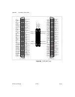
Figure B-1 is a simplified model of the M Series analog input timing
engine.
Figure B-1.
M Series Analog Input Timing Engine
The following signals are used in Figure B-1 and in the following sections:
•
Terminal
—Refers to any device terminal, such as PFI or RTSI. These
terminals are used as inputs and as outputs for signals.
•
_i
—Refers to any internal signal available to the analog input timing
engine for use. In the case of signals coming from an external terminal,
this would be the signal after is been through the first input buffer.
_i also can refer to other internal signals such as internal timebases or
signals coming from other blocks.
•
POUT
—Refers to any output signal right before is driven to an output
terminal.
•
Convert Clock Timebase and Sync Convert Clock
Timebase
—Convert Clock Timebase is the source signal used to
generate the signal that will actually cause the ADC to do a conversion
(p_AI_Convert). This signal can be an internal or external timebase
Start
Terminal
Selected Reference Trigger
Reference Trigger
Terminal
Terminal
Selected Sample Clock
Terminal
Terminal
Terminal
Selected Start
RTSI
Terminal
Terminal
Terminal
Selected Pause Trigger
SI
Counter
Block
SI2
Counter
Block
SI_TC
Sample Clock Timebase
Sync Sample Clock Timebase
Convert Clock Timebase
SI Start
Pause Trigger
SI2_TC
p_AI_Convert
Start
1
(and Other Counters,
and Such of Timer Core)
POUT
POUT
POUT
POUT
POUT
POUT
Sync Convert Clock Timebase
_i
_i
_i
_i
_i
_i
_i
_i


