background image

with the same file name in the same folder location so the sequence file can load it
correctly.

Related Information

mmWave OTA Validation Positioner Control Panel

 on page 35

Visualizing Measurements

 on page 38

Programming

Soft Front Panels

mmWave OTA Validation Positioner Control Panel

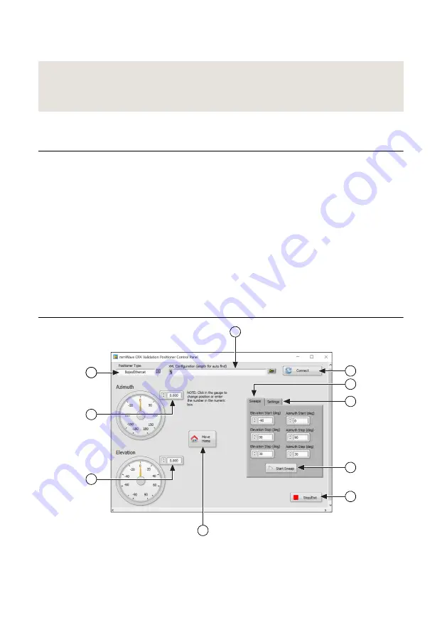
The mmWave OTA Validation Positioner Control Panel allows you to quickly manipulate the
positioner.

You can complete the following tasks with the mmWave OTA Validation Positioner Control
Panel:

Move the azimuth or elevation independently

Configure a sweep in both azimuth and elevation

Configure the Absolute Zero location of the positioner for antenna alignment

Figure 11. mmWave OTA Validation Positioner Control Panel Environment

1

10

8

2

3

4

1

9

5

6

7

1.

XML Configuration

—Browse to the file location of the XML configuration you want to

load. Leave the field blank to automatically detect the file location.

2.

Positioner Type

—Select the positioner used with your configuration.

mmWave OTA Validation Test Reference Architecture

  | 

© National Instruments Corporation

  | 

35

Summary of Contents for mmWave OTA

Page 1: ...on Anechoic Chamber and instrumentation with the mmWave OTA Validation Test Software Notice The protection provided by this equipment may be impaired if it is used in a manner not described in the documentation Contents Hardware Overview 2 Software Overview 2 Chamber Overview 5 Chamber Exterior 5 Chamber Interior 9 Getting Started 12 What You Need to Get Started 12 Operating the Chamber 14 Verifyi...

Page 2: ...ic Chamber options unless otherwise noted DFF Content applies to the DFF chamber CATR Content applies to the CATR chamber Note This manual contains only detailed reference information for using the mmWave OTA Validation Anechoic Chamber with the instrumentation Refer to the documentation for the individual instruments for basic information about installation configuration and operation of each ins...

Page 3: ...mmWave OTA Validation Visualizer Use the mmWave OTA Validation Visualizer to complete offline analysis of the test data for antenna measurements mmWave OTA Validation Positioner Control Panel Use the mmWave OTA Validation Positioner Control Panel to control the movement of the positioner Positioner Modes of Operation The 3GPP standard for OTA test of 5G NR DUTs requires making power measurements i...

Page 4: ...omization NI provides the source code for the plugins The following plugins are installed with the mmWave OTA Validation Test Software Antenna Control An API framework that allows you to create a plugin to control your specific active antenna module Positioner Control An API that allows you to use a different positioner with the mmWave OTA Validation Anechoic Chamber If your application requires a...

Page 5: ...Control Panel on page 35 RFmx Soft Front Panels on page 36 OTA Measurement Interface on page 46 Antenna Plugin on page 47 OTA API Reference Chamber Overview Chamber Exterior Top Bulkhead Notice To avoid damage to chamber connectors connect only cables that have the correct connector type 1A 2A 1B 2B 1A 2A 1B 2B 3A 4A 3B 4B VHD CI RJ45 1 USB 2 0 1 VGA RESE T A M E ST OP Butt on 15 1 DC USB 3 0 2 0 ...

Page 6: ...45 1 USB 2 0 1 VGA RESE T A M E ST OP Butt on 15 1 DC USB 3 0 2 0 RF filte r The rma l T Typ e 1 2 1A 2A 1B 2B VHDCI RJ45 1 USB2 0 1 VGA RESET A M E STOP Button 15 1 Table 2 Connector Descriptions Connector Connector Type Use VHDCI VHDCI Connects to the PXIe 6361 Multifunction I O Module VHDCI connector for data acquisition of the state of the positioner This is required for autonomous operation R...

Page 7: ...ion Rear Bulkhead 1A 2A 1B 2B 1A 2A 1B 2B 3A 4A 3B 4B DC USB3 0 2 0 RF filter Thermal T Type 1 2 1A 2A 1B 2B DC USB 3 0 2 0 RF filte r The rma l T Typ e 1 2 1A 2A 1B 2B VHD CI RJ45 1 USB 2 0 1 VGA RESE T A M E ST OP Butt on 15 1 Table 3 Connector Descriptions Connector Connector Type Use DC RF Filter Eight 4A 24 V filtered DC connectors 5 08 mm 8 position Supplies power to the DUT or other interna...

Page 8: ...USB Supplies a filtered USB connection into the chamber for any DUT needs Use the USB 3 0 1 5 m maximum length cable included in the chamber shipping kit to connect the chamber to your PC Note Use the AC switch on the rear of the chamber to power on the system Related Information External Connections on page 15 Operating the Chamber on page 14 8 ni com mmWave OTA Validation Test Reference Architec...

Page 9: ...multiple antennas to support multi antenna positions at equidistant places from the DUT center of rotation it holds only one antenna for the mmWave OTA Validation Test Reference Architecture Related Information Internal Connections on page 19 mmWave OTA Validation Test Reference Architecture National Instruments Corporation 9 ...

Page 10: ...a in the CATR chamber should only be detached and or mounted by NI services personnel Contact the NI services personnel contracted on your project to request these services for your CATR chamber Related Information Internal Connections on page 19 10 ni com mmWave OTA Validation Test Reference Architecture ...

Page 11: ...oner so the y axis points toward the measurement antenna Elevation θ Rotation The arrow points in a positive direction for the positioner 90 in elevation rotates the positioner so the z axis points toward the measurement antenna Related Information mmWave OTA Validation Positioner Control Panel on page 35 Visualizing Measurements on page 38 mmWave OTA Validation Test Reference Architecture Nationa...

Page 12: ...enna pattern test Getting Started with Step by Step Position Sweeping on page 30 7 Perform a fast full antenna pattern test Getting Started with Autonomous Position Sweeping on page 32 What You Need to Get Started Depending on your application you may require a different variation of the items listed below Contact the NI services personnel contracted on your project to help you determine which var...

Page 13: ...463 01 Required Instrumentation PXIe 5831 Vector Signal Transceiver IF and mmWave instrument configuration with two mmRH 5582 modules direct TRX ports only PXIe 1092 or PXIe 1095 PXI Chassis PXI Express embedded controller or MXI controller system that meets the system requirements specified in the chassis documentation AC power cable Optional Items 0 9 N m 8 lb in calibrated torque wrench 5 16 in...

Page 14: ...r Door During Operation It is important that the chamber door remain closed when you are performing a test If the key switch is set to Auto and you open the door during operation all movement in the chamber stops and you must press Reset to return the chamber to the default state No action is required if the key switch is set to Manual and you open and close the door during operation Related Infor...

Page 15: ...be found or is incorrectly configured contact NI to restore the original settings Verifying System Setup Before you begin using the mmWave OTA Validation Anechoic Chamber refer to the following sections to verify the external and internal hardware connections configure instrument settings in Measurement Automation Explorer MAX and connect the chamber to a client PC External Connections The externa...

Page 16: ... REF PWR 30 dBm 30 dBm PMAX 36 dBm PMAX 36 dBm 0 0 1 1 8 7 3 4 6 5 2 1 Figure 2 CATR Chamber Connected to Instrumentation PS TEMP FANS PXIe 1095 18 17 16 15 14 13 12 11 10 9 8 7 H H H H H 6 5 4 3 2 1 NI PXIe 8880 Embedded Controller GPIB DRIVE PWR OK FAULT USER1 USER2 10 100 1000 ACT LINK 10 100 1000 ACT LINK TRIG RESET 1 2 DP CONNECTOR 2 AI 80 143 CONNECTOR 2 AI 80 143 CONNECTOR 0 AI 0 15 AO DIO ...

Page 17: ... 85 mm cable CATR A 3 dB attenuator connects to the first mmRH 5582 module TRX Port 1 which then connects to the chamber rear bulkhead 2B port using a 2 92 mm m to 2 4 mm f adapter and 23 6 in 2 4 mm to 2 4 mm cable 5 A 3 dB attenuator connects to the second mmRH 5582 module TRX Port 0 which then connects to the chamber rear bulkhead 1A port using a 48 in 2 4 mm to 2 4 mm cable 6 A 3 dB attenuator...

Page 18: ...Configuring Settings in MAX You must configure and rename your instruments in Measurement Automation Explorer MAX before you begin taking measurements 1 Launch MAX 2 In the configuration tree expand Devices and Interfaces to see the list of installed NI hardware Installed instruments appear under the name of the associated chassis 3 Within the Settings section for each instrument enter the new nam...

Page 19: ...pplicable for both the CATR and DFF chambers unless otherwise noted Related Information DFF Chamber Interior on page 9 CATR Chamber Interior on page 10 Connecting Internal RF Cables 1 Connect one end of two 2 4 mm m to 2 4 mm m cables to the interior chamber rear bulkhead 1A and 2A ports 2 Route the opposite end of the cables through the correct locations on the positioner as shown in the followin...

Page 20: ...g if not properly managed Attaching the Reference Antenna The reference antenna verifies the functionality and integrity of the system during system calibration and ensures that the system is ready for testing your DUT 1 Mount the reference antenna to the azimuth axis as shown in the following figure 20 ni com mmWave OTA Validation Test Reference Architecture ...

Page 21: ...ioner Control Panel to rotate the positioner so the reference antenna points straight up toward the measurement antenna as shown in the previous figure Related Information Performing System Calibration on page 26 mmWave OTA Validation Positioner Control Panel on page 35 Positioner Coordinate System on page 11 DFF Chamber Internal Connections You must attach the measurement antenna and perform ante...

Page 22: ...e cable connected to the interior chamber top bulkhead 1A port to port H on the antenna 4 Connect the opposite end of the cable connected to the interior chamber top bulkhead 2A port to port V on the antenna Aligning the Reference and Measurement Antennas DFF Content applies to the DFF chamber Antenna alignment improves the repeatability and accuracy of your test The reference antenna data assumes...

Page 23: ...up toward the measurement antenna then set the Azimuth so the arrow on the positioner rotor points to 0 on the positioner dial scale as shown in Attaching the Reference Antenna on page 20 3 Attach the calibration laser to the laser alignment fixture and plug the laser USB cable into the USB port inside the chamber 4 Secure the laser alignment fixture to the measurement antenna fixture using an All...

Page 24: ...ser USB cable into the USB port inside the chamber 7 Use the mmWave OTA Validation Positioner Control Panel to move the laser until it is aligned to the center of the cross marker on the measurement antenna fixture 8 When the laser cross hits the center of the cross marker add 90 to the current Elevation number and click the Set Absolute Home button on the Settings tab in the mmWave OTA Validation...

Page 25: ... antennas Ensure the feed antenna and reflector are properly aligned by NI services personnel If anything has come into contact with the feed antenna or reflector and you think the parts are misaligned contact your NI services personnel for support Visually inspect the feed antenna and reflector for damage Complete the steps in Attaching the Reference Antenna on page 20 Ensure the chamber door is ...

Page 26: ...system requires IF calibration NI recommends performing system calibration in any of the following situations After any module in the chassis is installed uninstalled or moved After inter module cabling has been changed reconnected or repositioned After changing controllers computers or reinstalling software After self calibration is performed on the individual instruments The following components...

Page 27: ...rces and resource settings are correct for the path loss characterization as shown in the following figure Ensure the resource name for the power meter matches the name used in MAX Figure 9 Resources Window By default Self Calibrate Analyzer and Self Calibrate Generator are not selected NI recommends that you follow the calibration recommendations in the PXIe 5831 Specifications document and to pe...

Page 28: ...accessible through the embedded QR code on the antenna The gain values are converted into an XML file that the software can read 10 To accept all calibration settings click Calibrate Note Refer to Advanced System Calibration Settings on page 30 for more information about configuring advanced settings 11 When the Connect Power Meter Dialog box appears complete the following steps a Disconnect the 2...

Page 29: ...he antenna as shown in the following figure The calibration laser fixture should face the chamber door and the laser should point up toward the measurement antenna d Click Continue 13 When the MeasAntennaV dialog box appears set the Azimuth to 0 in the mmWave OTA Validation Positioner Control Panel to rotate the antenna as shown in the following figure then continue with calibration This ensures t...

Page 30: ...RF state of the instrument Analyzer Paths The analyzer measures two signal analyzer SA paths The reference antenna RA values are de embedded so the SA path loss includes the loss between the end of the RA and the SA instrument Analyzer Calibration Settings The frequency spacing settings including levels at which to calibrate are selected by default For OTA it is important to set the reference leve...

Page 31: ...on File from the menu 6 Select the Step_by_Step_NR csv file and click OK to save the current settings to the configuration file 7 Execute the test using the preferred programming interface Notice Verify that nothing interferes with the motion of the positioner The sequence triggers motion which may cause damage if anything interferes with the positioner Interface Task LabVIEW 1 In the mmWave OTA V...

Page 32: ...a pattern and review the NR measurements results of the antenna To verify the accuracy of the test refer to Performing System Calibration on page 26 Tip NI recommends familiarizing yourself with the example sequences When you save the example sequence as a new file you must also save the configuration file with the same file name in the same folder location so the sequence file can load it correct...

Page 33: ... the Autonomous_NR csv file located at NIDocDir TestStand 20xx 64 bit Examples OTA Test Sequences and click OK 4 Browse to the location of the Results File or use the default location from the example configuration file If the Resource Name is correct the RFmx SFP launches and displays the preconfigured NR measurement settings 5 Without closing the RFmx SFP return to the mmWave OTA Validation Conf...

Page 34: ...nts National Instruments OTA Test Examples DotNET VS20xx OtaTestExample bin Release 5 Enter the following text into the command prompt to run the OTA test OtaTestExample exe mode Autonomous input C Users Public Documents National Instruments TestStand 20xx 64 bit Examples OTA Test Sequences Autonomous_NR csv Note Append the following text to the previous command to test the positioner without perf...

Page 35: ...ith the mmWave OTA Validation Positioner Control Panel Move the azimuth or elevation independently Configure a sweep in both azimuth and elevation Configure the Absolute Zero location of the positioner for antenna alignment Figure 11 mmWave OTA Validation Positioner Control Panel Environment 1 10 8 2 3 4 1 9 5 6 7 1 XML Configuration Browse to the file location of the XML configuration you want to...

Page 36: ...TA Validation Configurator Use the mmWave OTA Validation Configurator to configure execute and visualize your OTA test measurements Loading and Saving the Configuration File 1 Select OTA Open Configuration File from the mmWave OTA Validation Configurator header menu 2 Locate an existing OTA configuration CSV file then click OK If the configuration file has specified the corresponding RFmx NR measu...

Page 37: ...jacent Channel Power ACP Channel Power CHP Error Vector Magnitude EVM Occupied Bandwidth OBW Spectral Emission Mask SEM Tip For the Adjacent Channel Power measurement set the Sweep Time to 200 ms to avoid memory overflow when running in Autonomous Mode b After you configure all the measurement settings in the RFmx SFP do not close the RFmx SFP window and return to the mmWave OTA Validation Configu...

Page 38: ...lugin that you want to use for the test from the Antenna Plugin drop down menu 3 Configure the antenna beam index in the Antenna Beam Settings section Configuring Calibration Settings Complete the following steps to enable calibration of the test 1 On the Calibration tab enter the name of the port name in the SGCalConfiguration and SACalConfiguration sections Use the same port names used for Syste...

Page 39: ...of your measurement results file Related Information Understanding the Measurement Results File on page 45 mmWave OTA Validation Visualizer Environment The following figure illustrates the elements of the mmWave OTA Validation Visualizer 1 3 2 4 1 Configuration tab Select the Measurement Result file choose the Measurement Type and configure the Data Selection settings for the visualization 2 Cut A...

Page 40: ...in LabVIEW options such as exporting the image or the plot data Note The examples below use a file that contains multiple beams to depict how the beams are displayed on each graph However all visualizations can also work with only one beam 1D Cut Analysis Visualization Example Cut Analysis Single Beam Cut Analysis All Beams 40 ni com mmWave OTA Validation Test Reference Architecture ...

Page 41: ...Polar Plot Visualization Example Polar Plot Single Beam 3D Pattern Plot Single Beam mmWave OTA Validation Test Reference Architecture National Instruments Corporation 41 ...

Page 42: ...Polar Plot Visualization Example 3D Pattern Plot All Beams 42 ni com mmWave OTA Validation Test Reference Architecture ...

Page 43: ...Heat Map Visualization Example Heat Map Single Beam Heat Map All Beams mmWave OTA Validation Test Reference Architecture National Instruments Corporation 43 ...

Page 44: ...ex All Beams gray codes the indices for the different selected indices In an ideal scenario the beam you selected should be the best for the direction that it was intentionally created for However in certain cases the index that best suits the direction is not the expected index The visualization makes it easier to quickly detect a problem with your codebook 44 ni com mmWave OTA Validation Test Re...

Page 45: ...ta section includes measurement data that is not specific to azimuth or elevation angles and Spatial Data includes measurement data that is valid at different azimuth and elevation angles Refer to the following tables for more information about each measurement Table 5 Non Spatial Data Measurements Measurement Description BeamPeakPower Absolute power at the beam peak BeamPeakAzimuth Azimuth of the...

Page 46: ...ent EVM Peak Maximum of EVMs in percent SEMMargin Worst case margin in dB SEMStatus Whether the power is within the standard defined limit SingleTone Single tone waveform peak power in dBm Note Refer to the RFmx NR Help for more information about specific measurements OTA Measurement Interface The OTA Measurement Interface OTAMI is the primary interface for your measurement data Use the OTAMI to s...

Page 47: ...ct library from the new class then add the packed project library and its corresponding configuration file into the following location NIDir LabVIEW 20xx user lib OTA Test Plugins Antennas PPL Refer to the SimulationAntenna folder for an example antenna plugin Note The plugin implementation uses the ESF Framework which enables LabVIEW objects to be to be instantiated as sessions The primary benefi...

Page 48: ...on is subject to change without notice Refer to the NI Trademarks and Logo Guidelines at ni com trademarks for information on NI trademarks Other product and company names mentioned herein are trademarks or trade names of their respective companies For patents covering NI products technology refer to the appropriate location Help Patents in your software the patents txt file on your media or the N...

Reviews: