20
|
ni.com
NI ISM-7400 User Manual
Power Dissipation
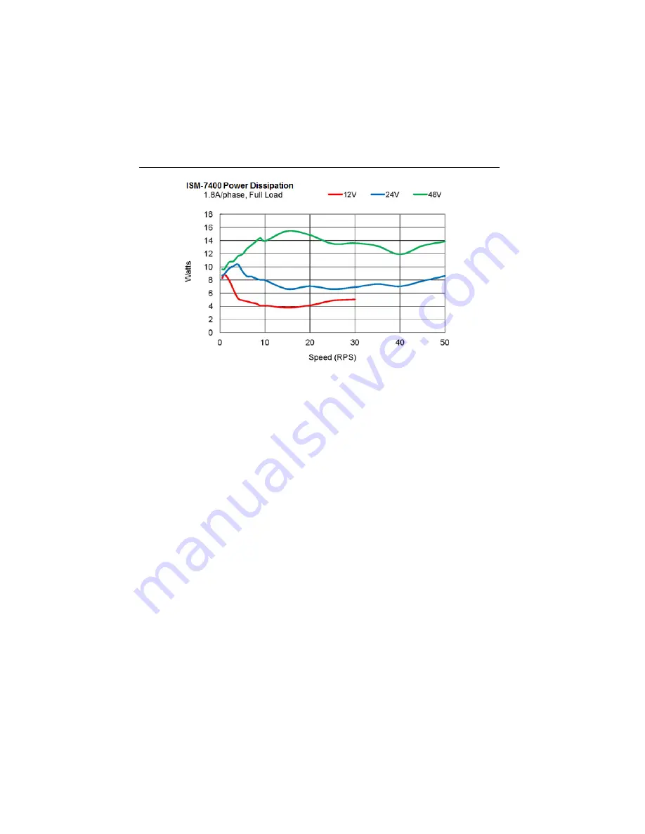
Figure 30.
Power Dissipation for the NI ISM-7400
Page 1: ...tion Examples STEP DIR 8 Connection Examples EN 9 Connecting the Digital Output 10 Using the Optional Encoder 11 Configuring the NI ISM 7400 12 Setting the Current 12 Setting Idle Current 12 Load Inertia 13 Step Size 13 Step Pulse Type 16 Step Pulse Noise Filter 16 Self Test 17 Reference Materials 18 Torque Speed Curves 18 Heating 18 Mechanical Outlines 21 Technical Specifications 23 Amplifier 23 ...
Page 2: ...ed the following items to get started with your NI ISM 7400 12 VDC to 48 VDC power supply NI PS 12 NI part number 748906 01 or NI PS 13 NI part number 748907 01 recommended Source of step signals such as a PLC or motion controller Refer to Choosing a Power Supply for more information ...
Page 3: ...s cause the surrounding air to be higher than 40 C Caution Never put the NI ISM 7400 where it can get wet or where metal or other electrically conductive particles can contact the circuitry Caution Always provide air flow around the drive When mounting multiple NI ISM 7400 integrated steppers near each other maintain at least one half inch of space between devices Connecting the Power Supply Refer...
Page 4: ...at load transfers back to the power supply This transfer can trigger the overvoltage protection of a switching power supply causing it to shut down Unregulated power supplies generally do not have overvoltage protection and have large capacitors for storing energy coming back from the drive NI offers the SMD 7700 regeneration clamp part number 748908 01 to solve this problem Choosing a Power Suppl...
Page 5: ...NI ISM 7400 User Manual National Instruments 5 Current The following charts list the maximum current required for each motor at several common power supply voltages ...
Page 6: ...ith significant regeneration as they generally do not have overvoltage protection and have large capacitors for storing energy coming back from the drive Refer to Connecting the Power Supply for more information Connecting Input Signals The NI ISM 7400 has three inputs STEP High speed digital input for step pulse commands 5 V to 24 V logic DIR High speed digital input for the direction signal 5 V ...
Page 7: ...NI ISM 7400 User Manual National Instruments 7 Figure 4 Connector Pin Diagram Figure 5 Internal Circuit Diagram ...
Page 8: ...8 ni com NI ISM 7400 User Manual Figure 6 Mating Cable Diagram Connection Examples STEP DIR Figure 7 Connecting to Indexer with Sourcing Outputs Figure 8 Connecting to Indexer with Sinking Outputs ...
Page 9: ...uses the drive to disable when the relay is closed and enable when the relay is open Figure 10 Connecting an Input to a Switch or Relay Connecting the Enable signal as shown in Figures 11 and 12 causes the drive to disable when the proximity sensor activates Figure 11 Connecting an NPN Type Proximity Sensor to an input Figure 12 Connecting a PNP Type Proximity Sensor to an input ...
Page 10: ...he inputs of other electronic devices like PLCs The positive collector and negative emitter terminals of the output transistor are available at the connector This allows you to configure the output for current sourcing or sinking Diagrams of each type of connection follow Caution Do not connect the output to more than 30 VDC The current through the output terminal must not exceed 80 mA Figure 14 S...
Page 11: ...rformance To facilitate connecting the encoder signals to your external controller you should purchase cable part number 748995 01 Note Maximum noise immunity is achieved when the differential receiver is terminated with a 110 Ω resistor in series with a 0 0047 μF capacitor placed across each differential pair The capacitor simply conserves power otherwise power consumption would increase by appro...
Page 12: ... is reduced to 70 and the heating to about 50 Switches 1 and 2 on the front of the NI ISM 7400 control the percent of rated current that will be applied to the motor Set them according to the illustration below Figure 18 Configuring Current on Switches 1 and 2 Setting Idle Current You can also reduce motor heating and power consumption by lowering the motor current when it is not moving The NI ISM...
Page 13: ...gly as shown below Figure 20 Configuring Load Inertia on Switch 7 Step Size The NI ISM 7400 requires a source of step pulses to command motion This may be a PLC an indexer a motion controller or another type of device The device must be able to produce step pulses with a frequency proportional to the desired motor speed The source must also be able to smoothly ramp the step speed up and down to pr...
Page 14: ...14 ni com NI ISM 7400 User Manual Select the steps per revolution setting that best suits your system capabilities Figure 21 Configuring Step Size on Switches 1 2 3 and 4 ...
Page 15: ...emulation also called step smoothing that can provide smooth motion when using full and half steps Set switch 6 to the ON position as shown in the figure below to provide the smoothest possible motion when using full and half steps Figure 22 Configuring Step Smoothing on Switch 6 The step smoothing process uses a command filter which causes a slight delay or lag in the motion The following graph s...
Page 16: ...al to the DIR input Figure 24 Configuring Step Pulse Type on Switch 8 Step Pulse Noise Filter Electrical noise can negatively affect the STEP signal by causing the drive to interpret one step pulse as two or more pulses This results in extra motion and inaccurate motor and load positioning To solve this problem the NI ISM 7400 includes a digital noise filter on the STEP and DIR inputs The default ...
Page 17: ...requency Self Test If you are having trouble getting your motor to turn you may want to try the built in self test Anytime switch 4 is moved to the ON position the drive will automatically rotate the motor back and forth two and a half turns in each direction This feature can be used to confirm that the motor is correctly wired selected and otherwise operational Figure 26 Configuring Self Test on ...
Page 18: ...0 also dissipate power The heat produced by the electronics is dependent on power supply voltage and motor speed The following figure show the maximum duty cycle versus speed for each motor at commonly used power supply voltages Refer to these curves when planning your application Charts depicting typical power dissipation are also provided for use in planning the thermal design of your applicatio...
Page 19: ...0 in a 40 C 104 F environment with the motor mounted to an aluminum plate sized to provide a surface area consistent with the motor power dissipation Your results might vary Maximum Duty Cycle Figure 28 Duty Cycle for the ISM 7400 Power Consumption Figure 29 Power Consumption for the NI ISM 7400 ...
Page 20: ...20 ni com NI ISM 7400 User Manual Power Dissipation Figure 30 Power Dissipation for the NI ISM 7400 ...
Page 21: ...NI ISM 7400 User Manual National Instruments 21 Mechanical Outlines Figure 31 Mechanical Outline for the NI ISM 7400 ...
Page 22: ...22 ni com NI ISM 7400 User Manual Figure 32 Mechanical Outline for the NI ISM 7400D ...
Page 23: ...fier Digital MOSFET 16 kHz PWM Protection Over voltage under voltage over current over temperature Supply voltage 12 VDC to 48 VDC Under voltage alarm 10 VDC Over voltage shutdown 53 VDC Over temp shutdown 85 C Motor current 1 0 to 2 0 A phase peak of sine four settings via DIP switches Motor Torque Refer to Torque Speed Curves ...
Page 24: ...odarlington 80 mA 30 VDC max Voltage drop 1 2 V max at 80 mA Physical Dimensions 1 71 2 20 2 64 in 5 mm shaft with flat 43 5 56 67 mm overall not including pilot or shaft Weight 14 7 oz 416 g Rotor inertia 1 16 10 to 3 oz sec2 82 g cm2 Operating temperature range 0 C to 40 C Incremental Encoder Specifications 10 pin connector signals pin assignments Ground 1 2 Index 3 Index 4 A 5 A 6 5VDC power 7 ...
Page 25: ...mber 748907 01 Alarm Codes In the event of a drive fault or alarm the green LED flashes one or two times followed by a series of red flashes The pattern repeats until the alarm is cleared Table 1 Status LED Blink Code Definitions Blink sequence Code Error G Solid green No alarm motor disabled GG Flashing green No alarm motor enabled RR Flashing red Configuration or memory error RRRG 3 red 1 green ...
Page 26: ...d Services The National Instruments website is your complete resource for technical support At ni com support you have access to everything from troubleshooting and application development self help resources to email and phone assistance from NI Application Engineers Visit ni com services for NI Factory Installation Services repairs extended warranty and other services Visit ni com register to re...