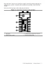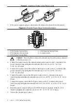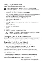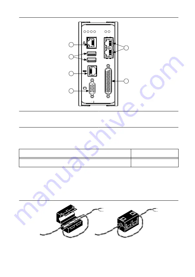
Figure 2. IC-3120 Front Panel Connectors
RESET
DIGIT
AL I/O
10/100/
1000
ACT/
LINK
USER1
USER2
PWR/
FA
UL
T
ST
A
TUS
P
oE0
P
oE POR
T 0
P
oE POR
T 1
P
oE1
5
3
6
1
2
4
IC-3120
Industrial Controller
1. VGA Connector
2. RJ50 Serial Port
3. USB 2.0 Ports
4. RJ45 Network Port
5. Gigabit Ethernet PoE Ports
6. 44-pin Digital I/O Connector
Connecting the System Power Supply
NI recommends the following power supply for the IC-3120.
Power Supply
Part Number
NI PS-15 Industrial Power Supply
781093-01
Complete the following steps to supply power to the IC-3120.
1.
Verify the power source is turned off.
2.
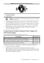
Install one ferrite across the negative and positive leads of the power source,
approximately 50 to 75 mm (2 to 3 in.) from the end of the power input wires.
Figure 3. Installing a Ferrite on the Power Leads
3.
If the power connector plug is connected to the chassis, disconnect it from the device.
4
|
ni.com
|
IC-3120 Getting Started Guide

