using the NI 9401 for verification, refer to the
NI 9924 User Guide and Specifications
for
installation information.
Note
(cDAQ-9172)
You must install the C Series digital module in slot 5 or 6 of
the chassis.
Counter Verification
CompactDAQ chassis and controllers have only one timebase to verify, so only Counter 0
needs to be checked. It is not possible to adjust this timebase, so only verification can be
performed. Complete the following steps to verify the counter on the cDAQ chassis or
controller.
1.
Connect the external counter to the C Series digital module.
•
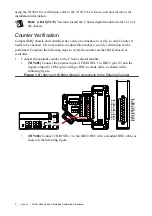
(NI 9401)
Connect the positive input of CHANNEL 1 to DIO 3 (pin 19) and the
negative input to COM (pin 1) using a BNC-to-leads cable, as shown in the
following figure.
Figure 1. NI 9401 and NI 9924 Signal Connections to the External Counter
SH
21
8
2
15
5
18
14
16
17
19
20
22
23
25
11
24
CHANNEL 1
CHANNEL 2
CHANNEL 3
1
3
4
6
7
9
10
12
13
COM
NC
COM
COM
NC
COM
COM
NC
COM
COM
NC
COM
COM
DIO0
NC
DIO1
DIO2
NC
DIO3
DIO4
NC
DIO5
DIO6
NC
DIO7
1
2
3
4
5
6
7
8
9
10
11
12
13
14
15
16
17
18
19
20
21
22
23
24
25
•
(NI 9402)
Connect CHANNEL 1 to the DIO 0 BNC with a standard BNC cable, as
shown in the following figure.
4
|
ni.com
|
cDAQ Chassis and Controllers Calibration Procedure


