Chapter 4
General-Purpose Counter/Timer
©
National Instruments Corporation
4-5
DAQ-STC Technical Reference Manual
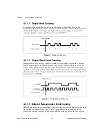
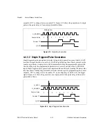
G_SOURCE signal after the software arm. Each active edge of the G_GATE signal latches
the count value for the current counting interval into the hardware (HW) save register and
reloads the counter with the initial value to begin the next counting interval. An interrupt
notifies the CPU after each counting interval so that the interrupt software can read the result
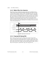
from the HW save register. Figure 4-4 shows buffered noncumulative event counting with two
counting intervals. Three events are counted in each of the two counting intervals.
Figure 4-4.
Buffered Noncumulative Event Counting
4.4.1.4 Buffered Cumulative Event Counting
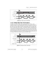
Buffered cumulative event counting is similar to simple event counting except that the
G_GATE signal indicates when to save the counter value to the HW save register. The active
G_GATE edge latches the count value into the HW save register. Counting continues
uninterrupted regardless of the G_GATE activity. An interrupt notifies the CPU after each
active G_GATE edge so that the interrupt software can read the result from the HW save
register. Figure 4-5 shows cumulative event counting where the gate action causes the HW
save register to save the counter contents twice.
Figure 4-5.
Cumulative Event Counting
Software Arm
G_SOURCE
G_GATE
Counter Value
HW Save Register
1
0
X
1
3
3
3
3
1
2
2
Software Arm
G_SOURCE
G_GATE
Counter Value
HW Save Register
1
0
X
7
6
3
6
3
4
5
2


