Chapter 3
Analog Output Timing/Control
©
National Instruments Corporation
3-85
DAQ-STC Technical Reference Manual
3.7.1.1 UPDATE_SRC
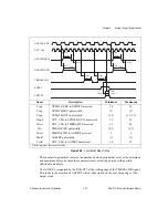
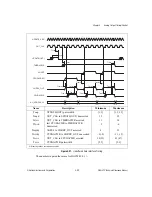
UPDATE_SRC represents the signal that causes an UPDATE to be generated. Table 3-2
indicates the pin represented by UPDATE_SRC based on internal selection.
3.7.1.1 UI2_SRC
UI2_SRC represents the signal that clocks the UI2 counter. Table 3-3 indicates the pin
represented by UI2_SRC based on internal selection.
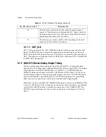
Table 3-2.
UPDATE_SRC Reference Pin Selection
AO_UPDATE_Source_Select
Reference Pin
0
The UPDATE source is selected to be UI_TC. The reference
pin is determined by AI_UI_Source_Select.
1–10
PFI<0..9>
11–17
RTSI_TRIGGER<0..6>
19
The UPDATE source is selected to be the output of
general-purpose counter 1. The reference pin is determined by
G1_Source_Select. To determine delays for this case, the
source to output delay (Tso) from general-purpose counter 1
must be added.
Table 3-3.
UI2_SRC Reference Pin Selection
AO_UI2_Source_Select
Reference Pin
0
The reference pin is OSC or RTSI_OSC, depending on the clock
mode you choose in RTSI_Clock mode.
1–10
PFI<0..9>
11–17
RTSI_TRIGGER<0..6>
19
The UI2 source is selected to be the output of general-purpose
counter 0. The reference pin is determined by G0_Source_Select. To
determine delays for this case, the source to output delay (Tso) from
general-purpose counter 0 must be added.


