Chapter 2
Analog Input Timing/Control
DAQ-STC Technical Reference Manual
2-104
©
National Instruments Corporation
Synchronous Mode
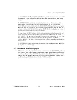
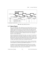
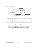
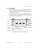
In synchronous mode, the STOP outputs change on the CONVERT source edge following a
change in the external trigger. Figure 2-36 shows the behavior of the STOP output in
synchronous mode.
Figure 2-36.
STOP Delay, Synchronous Mode
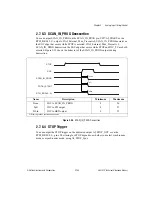
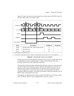
Asynchronous Mode
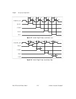
In asynchronous mode, the STOP outputs follow the external trigger. Figure 2-37 shows the
behavior of the STOP outputs in asynchronous mode.
Figure 2-37.
STOP Delay, Asynchronous Mode
Name
Description
Minimum
Maximum
Tstop
CONVERT_SRC to AI_STOP_OUT
12
44
Tbrd
CONVERT_SRC to BRD output
12
45
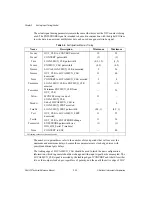
All timing values are in nanoseconds.
Name
Description
Minimum
Maximum
Tstst
STOP to AI_STOP_OUT
9
32
Tbrd
STOP to BRD output
10
33
All timing values are in nanoseconds.
STOP
CONVERT_SRC
AI_STOP_OUT
RTSI_BRD<0..1>
Tbrd
Tstop
Tbrd
Tstop
STOP
AI_STOP_OUT
RTSI_BRD<0..1>
Tbrd
Tstst
Tbrd
Tstst

