Drivven, Inc.
Throttle Driver Module Kit
© Drivven, Inc. 2009
• Throttle Driver Module Kit User’s Manual • D000017 • Rev B
20
deviation of Battery compared to BattNom. When FALSE, the throttle output will
not be compensated. Battery compensation has a small effect.
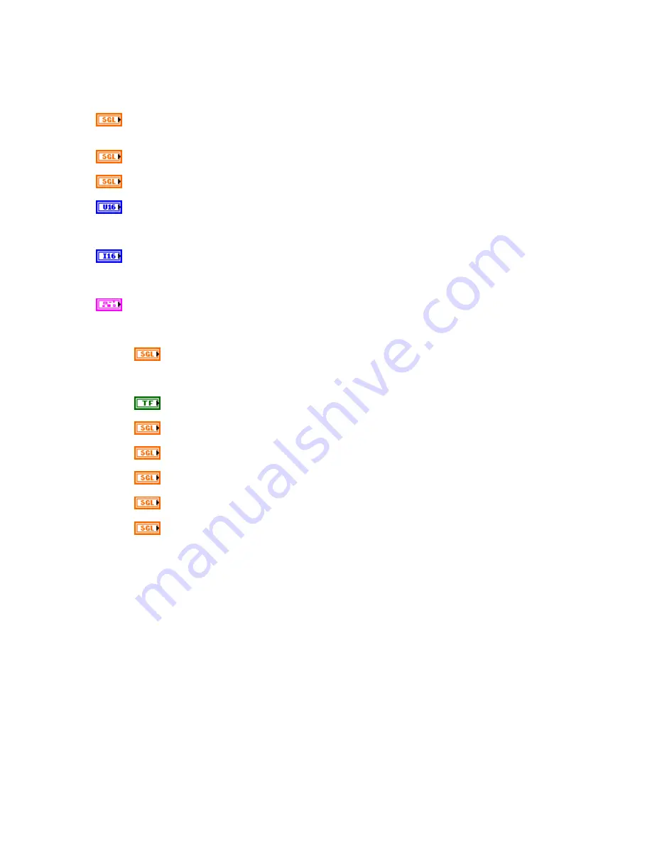
Theta (deg)
The latest feedback throttle angle (degrees) of the throttle body under
control.
ThetaR (deg)
The requested angle setpoint (degrees) of the throttle body under control.
dt (sec)
Interval (in seconds) at which this VI is called.
ThrottlePeriodTicks
Number of 4 MHz clock ticks required to achieve 500 Hz PWM
frequency to the h-bridge circuit. Should be wired to the FPGA to the throttle_revx.vi
ThrottleControl cluster for the desired channel.
ThrottlePulseWidthTicks
Signed integer of 4 MHz clock ticks required to achieve the
PWM duty cycle calculated by the throttle_rt_control.vi. Should be wired to the FPGA to
the throttle_revx.vi ThrottleControl cluster for the desired channel.
ThrottleControlCalcs
This output cluster is for monitoring purposes only. It provides the
latest values from the PID, Limp-Home Compensation and Stiction Compensation
algorithms.
ThetaFF (deg)
Value calculated by the Lead/Lag compensator function on
ThetaR. The effects of TLead and TLag can be seen on this parameter. This
parameter is the setpoint given to the throttle PID algorithm.
AboveLH?
Indicates whether Theta is above ThetaLH.
uLHc (V)
Limp-home region compensation added to PID calculation.
uFc (V)
Stiction compensation added to PID calculation.
uPID (V)
PID control result.
u (V)
Control value calculated from the sum of uPID, uLHc and uFc.
uBattComp (V)
Final control value compensated for actual battery voltage.


