background image

©

 National Instruments Corporation

3

NI cDAQ Chassis Calibration Procedure

Initial Setup

Refer to the 

DAQ Getting Started

 guides for instructions on installing the software, hardware, and 

configuring the NI cDAQ chassis. NI cDAQ-9188 users should refer to the 

NI cDAQ-9188 Ethernet 

Chassis Quick Start

.

Verification

This section provides instructions for verifying the counter on an NI cDAQ chassis.

1.

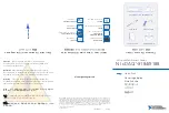
Connect the counter to the C Series digital I/O module. Refer to Figure 1 for a connection diagram 
of the NI 9401 and NI 9402.

a.

Connect the positive input of the counter to DIO 0 on the C Series module.

b.

Connect the negative input of the counter to COM or GND on the C Series module.

Figure 1.  

NI 9401 and NI 9402 Pin Assignments

2.

Create and configure a counter output channel according to Table 2.

3.

Start the generation of a square wave.

4.

Configure the counter to measure frequency and use a 1 M

Ω 

impedance.

5.

Take a measurement of the square wave.

6.

Compare the counter reading to the limits in Table 3.

Table 2.  

Counter Output Configuration

Frequency

Scaled 

Units

Idle 

State

Initial 

Delay

DAQmx Timing 

Instance

Generation 

Mode

Samples to 

Write

5000000

Seconds

Low

0

Implicit

Continuous 

Pulses

1000

Table 3.  

NI cDAQ Chassis Counter Limits

Set Point (MHz)

Lower Limit (MHz)

Upper Limit (MHz)

5

4.99975

5.00025

COM
NC
COM
COM
NC
COM
COM
NC
COM
COM
NC
COM
COM

DIO0
NC
DIO1
DIO2
NC
DIO3
DIO4
NC
DIO5
DIO6
NC
DIO7

1
2
3
4
5
6
7
8
9

10
11
12
13

14
15
16
17
18
19
20
21
22
23
24
25

DIO 3
GND

DIO 2

GND

DIO 0

NI 9402

NI 9401

GND

DIO 1
GND

Summary of Contents for cDAQ

Page 1: ...support for the ADE that you intend to use Documentation Requirements For information about NI DAQmx and NI cDAQ chassis you can consult the following documents DAQ Getting Started guides These guides provide instructions for installing and configuring NI DAQ devices NI DAQmx Help This help file contains general information about measurement concepts key NI DAQmx concepts and common applications t...

Page 2: ...ature will be greater than the ambient temperature Keep relative humidity below 90 Allow a warm up time of at least 10 minutes to ensure that the measurement circuitry is at a stable operating temperature Calibration Procedures The calibration process includes the following steps 1 Initial Setup Install the device and configure it in Measurement Automation Explorer MAX 2 Verification Verify the ex...

Page 3: ... the C Series module Figure 1 NI 9401 and NI 9402 Pin Assignments 2 Create and configure a counter output channel according to Table 2 3 Start the generation of a square wave 4 Configure the counter to measure frequency and use a 1 MΩ impedance 5 Take a measurement of the square wave 6 Compare the counter reading to the limits in Table 3 Table 2 Counter Output Configuration Frequency Scaled Units ...

Page 4: ...on development self help resources to email and phone assistance from NI Application Engineers National Instruments corporate headquarters is located at 11500 North Mopac Expressway Austin Texas 78759 3504 National Instruments also has offices located around the world to help address your support needs For telephone support in the United States create your service request at ni com support and fol...

Reviews: