


Getting Started with NI 9512 and P7000 Drives
|
© National Instruments
|
17
Encoderless Stall Detection
The P7000 series stepper drive is uniquely designed to sense the motor shaft position at all times.
The drive monitors the commanded position and compares it to the actual position. As with any
two-phase step motor, when the shaft position and commanded position are greater than two full
steps apart, a stall is detected, and the drive faults.
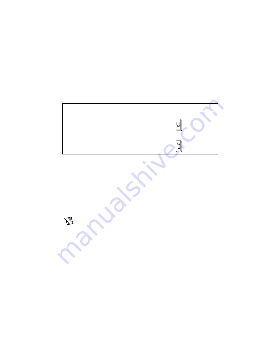
Table 11 lists the encoderless stall detection switch settings.
Encoderless stall detection uses an internal motor model for stall detection. Motors listed in
Tables 4 and 5 work well with encoderless stall detection. Third-party motors may not work as
well, as the algorithm is subject to constraints. National Instruments makes no guarantees of
reliability of this feature when using third-party motors.
Step 4: Connect the NI 9512 to the P7000 Drive
Use the direct connect cable to connect the NI 9512 to the P7000 drive.
1.
Connect the NI 9512 module DSUB connector to the P7000 series drive Command I/O
connector using the NI 9512-to-P7000 cable.
2.
Connect the power supply to the NI 9512-to-P7000 direct connect cable V
sup
inputs.
Note
Refer to the
Specifications
section of the
NI 9512 Operating Instructions and
Specifications
for power supply requirements.
3.
Connect the NI 9512 module MDR connector to the 37-pin terminal block using the
terminal block cable. Refer to Chapter 4,
Accessory and Cable Connections
, in the
NI 951x
User Manual
for cabling recommendations.
4.
Connect the limits, feedback, and other I/O signals to the 37-pin terminal block or custom
cable.
5.
Connect the drive power supply to the P7000 drive.
Table 11.
Encoderless Stall Detection DIP Switch Settings
Encoderless Stall Detection
S2–12
Enabled
ON
Disabled
OFF
12
O
N
12
O
F
F


