

NI 9237 Calibration Procedure
6
ni.com
Verification Procedure
Verification determines how well the device is meeting its specifications.
By completing this procedure, you can see how the device has drifted over
time, which helps you determine the appropriate calibration interval for
your application. Table 4 in the
settings for the device type. Throughout the verification process, use
Table 4 to determine if the device is operating within its specified range.
You must perform verification on all analog input channels.
Complete the following steps to test the performance of the device.
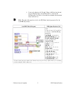
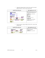
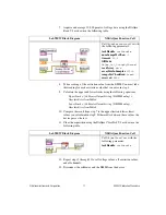
1.
Make the following connections on the NI 9949 terminal block:
•
Insert one leg of each 350
Ω
resistor into AI–.
•
Insert the second leg of one 350
Ω
resistor into EX+.
•
Insert the second leg of the other 350
Ω
resistor into EX–.
•
Connect RS+ to EX+.
•
Connect RS– to EX–.
•
Connect the positive input of the DMM to RS+.
•
Connect the negative input of the DMM to RS–.
•
Connect the positive output of the calibrator to AI+.
•
Connect the negative output of the calibrator to AI–.
•
Leave the SC, T+, and T– terminals unconnected.
•
If the calibrator has a separate guard connection not connected to
LO, connect that terminal to AI–.
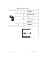
Refer to Table 2 for the pin assignments and signal names of the NI 9237.
Refer to Figure 1 for an illustration of the NI 9949 connections.


