

©
National Instruments Corporation
7
NI 9237 Calibration Procedure
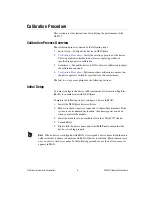
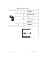
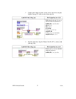
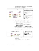
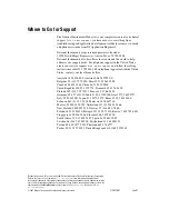
Figure 1.
NI 9949 Connections
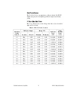
Table 2.
Pin Assignments and Signal Names
Module
RJ-50 Pin
Signal Name
Signal Description
1
SC
Shunt calibration
2
AI+
Positive analog input
3
AI–
Negative analog input
4
RS+
Positive remote sense input
5
RS–
Negative remote sense input
6
EX+
Positive excitation output
*
7
EX–
Negative excitation output
*
8
T+
TEDS DATA
9
T–
TEDS Return
*
10
SC
Shunt calibration
* These signals are shared by all four RJ-50 connectors on the NI 9237.
– +
–
+
EX+
RS+
RS–
EX–
DMM
AI–
Calibrator
Guard
AI+


