Chapter 2
Configuration and Installation
© National Instruments Corporation
2-5
SCXI-1100 User Manual
acquisition board controls the SCXIbus INTR* line. See the Timing Requirements and
Communication Protocol section later in this chapter, and Chapter 5, Programming, for
information on the use of the INTR* line. See Appendix E, SCXI-1100 Cabling, for the pin
equivalences of the SCXI-1100 rear signal connector and the data acquisition board I/O
connector.
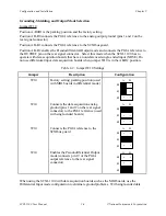
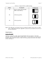
Do not use position B, which is reserved.
Table 2-1. Digital Signal Connections, Jumper Settings
Jumper
Description
Configuration
W5
Connects MISO to SERDATOUT;
factory-default setting
•
•
•
1
2
3
W5
Parking position
•
•
•
1
2
3
W6
Factory setting; do not remove this
jumper
•
•
•
3 2 1
W9
Connects pullup to SERDATOUT
(Revision C and higher modules only);
factory-default setting
•
•
•
1
2
3
W9
Parking position (not connected on
Revision A and B modules)
•
•
•
1
2
3
W11
Factory default (Revision A and B
modules only)
•
•
•
A B
Analog Configuration
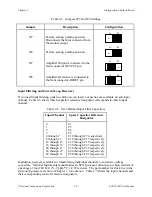
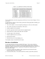
The SCXI-1100 has seven analog configuration jumpers–W10, W7, W8, W1, W2, W3, and W4.
Use these jumpers to configure the output mode, reference mode, filter selection, and amplifier
output selection.

