©
National Instruments Corporation
5
NI 1483R User Guide and Specifications
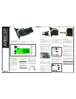
Figure 4.
Installing the NI 1483
2.
Tighten the captive screws on the NI 1483 to secure it to the NI FlexRIO FPGA module.
Step 3. Connect Signals
This section describes the Base configuration 26-pin SDR connector, the Medium/Full configuration
26-pin SDR connector, and the 15-pin D-Sub connector on the NI 1483.
SDR Connectors
Figure 5 shows the NI 1483 Base configuration 26-pin SDR connector assignments. Refer to Table 1 for
a description of the signals.
Figure 5.
NI 1483 Base Configuration SDR Connector Pin Assignments
1
NI FlexRIO Adapter Mod
u
le (NI 14
83
)
2
Captive Screw
3
G
u
ide Pin
4
PXI/PXI Express Chassis
5
NI FlexRIO FPGA Mod
u
le
PXI-1000B
5
1
3
4
2
DGND
X(0)+
X(1)+
X(2)+
XCLK+
X(3)+
S
erTC–
S
erTFG+
CC(1)+
CC(2)–
CC(3)+
CC(4)–
DGND
DGND
X(0)–
X(1)–
X(2)–
XCLK–
X(3)–
S
erTC+
S
erTFG–
CC(1)–
CC(2)+
CC(3)–
CC(4)+
DGND
13
12
11
10
9
8
7
6
5
4
3
2
1
26
25
24
23
22
21
20
19
18
17
16
15
14


