background image

Operation

8

excess damage in the event of an emergency. Lanyard must be worn by operator for 

this safety device to work properly. Pull key out to stop the machine motor.

Controller Settings

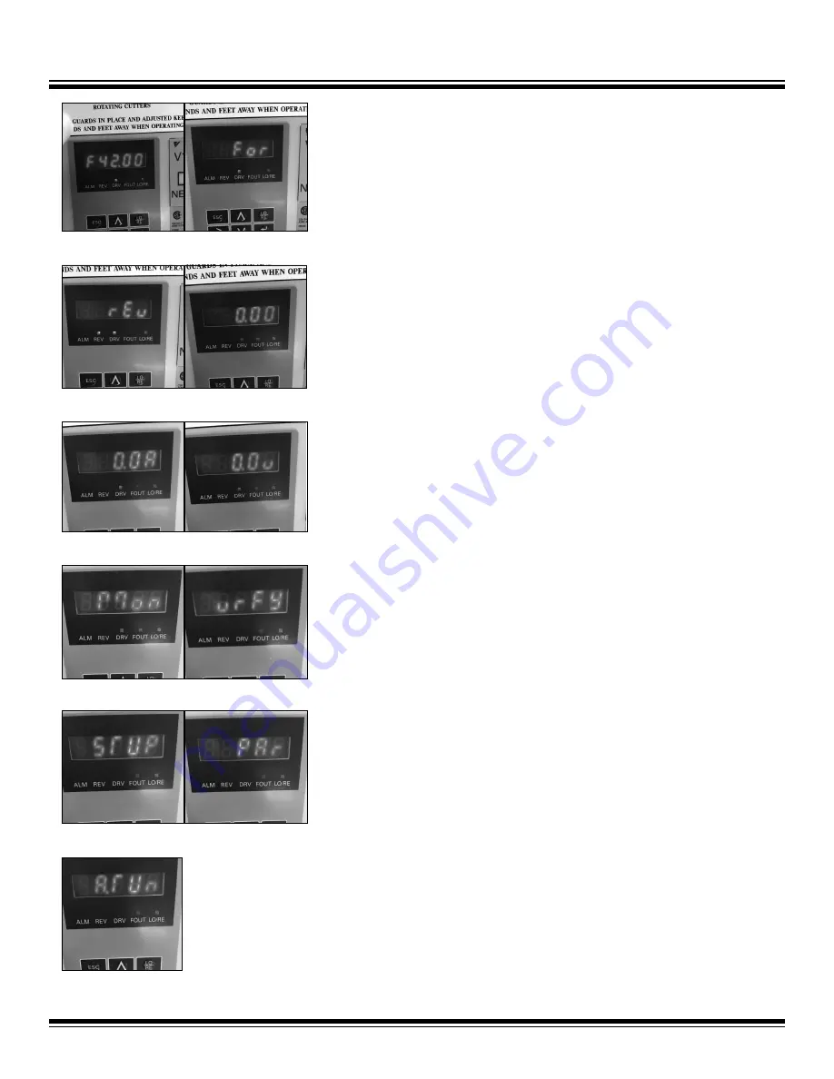
Below is a list of settings that the operator can scroll through on the controller, in order 

of appearance. Press up/down arrows until the desired parameter is shown.

•  “Fxx.xx” is the input frequency used to adjust tooling RPM (Figure 4).
•  “For” or “rEv” is used for changing the rotational direction of the tooling to forward 

or reverse (Figures 5 and 6).

•  “0.00” is the output frequency setting (Figure 7).
•  “0.0A” is the output current draw (Figure 8).
•  “0.0v” is the voltage output to the motor (Figure 9).

The following settings should not be selected or used by the operator:

•  “Mon” monitor display (Figure 10).
•  “vrFY” verify menu (Figure 11). 
• 

“STUP” setup mode (Figure 12).

•  “PAr” parameter setting mode (Figure 13).
•  “ATUn” auto-tuning (Figure 14). 

Input Frequency Setting

The input frequency (Figure 4) can be used as follows to adjust tooling RPM:

1.  Press the up/down arrows until “Fxx.xx” is shown, where xx.xx is some number.
2. 

Press “Enter;” the first digit will flash.

3. 

Press the up/down arrows until the desired number is shown for the first digit.

4.  To change any other digit, use the “>” key to select the digit, then press the up/

down arrows until the desired number is shown in that position.

5.  Press “Enter” then press “Esc.”

Setting the Tooling Rotational Direction

To set tooling rotational direction (Figures 5 and 6) to forward or reverse, complete the 

following steps:

1.  Press the up/down arrows until “For” or “rEv” is shown.
2. 

Press “Enter;” the letters will flash.

3.  Press the up/down arrows until the desired rotational direction is shown.
4.  Press “Enter,” then press “Esc.”

FIG. 4

FIG. 5

FIG. 6

FIG. 7

FIG. 8

FIG. 9

FIG. 10

FIG. 11

FIG. 12

FIG. 13

FIG. 14

To 

order 

go 

to 

Discount-Equipment.com

Summary of Contents for GP700

Page 1: ...Read Manual Before Operating Machine 403309 Rev D GP700 GRINDER INSTRUCTION MANUAL T o o r d e r g o t o D i s c o u n t E q u i p m e n t c o m...

Page 2: ...Curtis Gehl Pavers Heli Honda ICS PowerGrit IHI Partner Imer Clipper MMD Koshin Rice CH E General Equip ment Amida Coleman NAC Gradall Square Shooter Kent Stanley Tamco Toku Hatz Kohler Robin Wiscons...

Page 3: ...ontroller 8 Maintenance 9 Lubricating the Machine 9 Keeping Machine Clean 9 Replacing Worn Damaged Missing Parts 9 High Motor Temperature 9 Tooling Installation and Replacement 10 Accessing the Drive...

Page 4: ...3 A Manual foot leveling device Improved machine control faster and greater range of adjustments 6 leveling adjustments in 1 8 incre ments and simple to operate Lightweight machine For ease of transpo...

Page 5: ...on that may cause decreased control Keep hands away from all moving parts and tooling Wear gloves when changing tooling Remove tooling when ma chine is not in use and or lower cutting head to the floo...

Page 6: ...tooling and accessories Provide barriers or shields as needed to protect others from debris Use for correct applications Do not force equipment to do heavier duty work than it was made for Do not blo...

Page 7: ...handle in position START UP PROCEDURE 1 Ensure plug is connected properly to the power source 2 Ensure dust hose is connected correctly to dust collector and machine 3 Check that the main switch is t...

Page 8: ...gure 12 PAr parameter setting mode Figure 13 ATUn auto tuning Figure 14 Input Frequency Setting The input frequency Figure 4 can be used as follows to adjust tooling RPM 1 Press the up down arrows unt...

Page 9: ...D MISSING PARTS Morflex Couplings Bolts should be checked weekly for tightness Loose bolts cause extreme vibrations and premature failure of rubber inserts in the couplings Flexible couplings should b...

Page 10: ...n place 4 Grasp machine handle and lower machine to the floor slowly so that all diamonds are resting on the floor Make certain none have fallen or loosened while lowering the machine to the floor ACC...

Page 11: ...Parts List and Diagrams 11 T o o r d e r g o t o D i s c o u n t E q u i p m e n t c o m...

Page 12: ...Parts List and Diagrams 12 403627 403629 403628 T o o r d e r g o t o D i s c o u n t E q u i p m e n t c o m...

Page 13: ...403633 403616 LABEL 208 230V 3 PHASE ONLY 403715 1 PLUG MALE HUBBELL TWIST LOCK 3P4W 50A 3PH 250V AC 403754 1 PLUG FEMALE HUBBELL TWIST LOCK 3P4W 50A 3PH 250V AC 403753 1 T o o r d e r g o t o D i s...

Page 14: ...Curtis Gehl Pavers Heli Honda ICS PowerGrit IHI Partner Imer Clipper MMD Koshin Rice CH E General Equip ment Amida Coleman NAC Gradall Square Shooter Kent Stanley Tamco Toku Hatz Kohler Robin Wiscons...

Page 15: ...NATIONAL FLOORING EQUIPMENT T o o r d e r g o t o D i s c o u n t E q u i p m e n t c o m...

Reviews: