National Flooring Equipent 8274-4 Service Manual Download Page 9

Maintenance

9

BELT PROCEDURES

Note:


Blue Loctite should be used on tensioner bolts. Torque on 3/8” bolts should not 

exceed 25 lbs.

To Access Belt

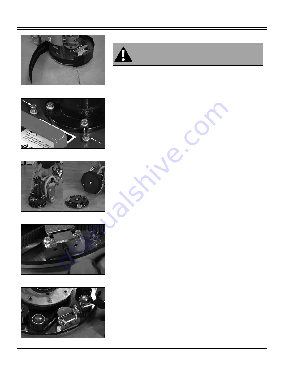
1.  Remove dust guard (Figure 1).
2.  Remove the four bolts on top of the shroud cover (Figure 1.1).
3.  Push down on the handle. The shroud should lift up and away from the grinding 

deck. If not, with the four bolts on top of the shroud cover removed, tip the grinder 

deck back to the tool changing position. Insert a 1/2”-13x4” threaded bolt into the 

center of the underside of the deck plate. Turn bolt in clockwise until deck is free of 

grinder shroud. Remove bolt and the shroud should now lift up and away from the 

grinding deck (Figure 1.2).

4.  Move machine back and off the plate (Figure 1.3).

Removing Belt

1.  Remove any dust or debris from inside the deck.
2.  Using an Allen wrench, install the 5/16-18x1 1/4” socket head cap screws into each 

tensioner and compress the block spring by turning the screw clockwise. The belt 

should be loose enough to slide off.

3.  Leave approximately 1/8” gap when compressing the block spring to allow clear-

ance for removing the tensioner mounting bolts (Figure 2).

4.  Remove one mounting bolt completely; loosen the other (Figure 3).

FIG. 1

FIG. 1.1

FIG. 1.2

FIG. 2

FIG. 3

CAUTION:

 BEFORE ANY MAINTENANCE, MAKE SURE MACHINE IS DISCON-

NECTED FROM POWER SOURCE

FIG. 1.3

Summary of Contents for 8274-4

Page 1: ...Read Manual Before Servicing Machine 402973 Rev B 8274 4 PLANETARY GRINDER SERVICE MANUAL...

Page 2: ......

Page 3: ...le of Contents 3 Table of Contents 3 Specifications 4 Safety 6 Troubleshooting Guide 7 Maintenance 8 General Maintenance 8 Belt Procedures 9 Complete Parts List 14 Parts List and Diagrams 15 Warranty...

Page 4: ...quency HP Motor 20 51 cm 27 5 52 70 132 cm 38 5 75 98 190 5 cm 388 lbs 176 kg 18 5 47 cm 120 V 60 Hz single phase input 3 3 Phase operation Adjustable Handle 90 Rotating Grinder Deck Control Box Adjus...

Page 5: ...chine is not in use and or lower cutting head to the floor Do not force equipment Equipment will perform best at the rate for which it was designed Excessive force only causes operator fatigue increa...

Page 6: ...ter stopping the machine Use correct tooling and accessories Provide barriers or shields as needed to protect others from debris Use for correct applications Do not force equipment to do heavier duty...

Page 7: ...heating due to using too long of an extension cord or because the outlet generator is the wrong voltage Allow motor to cool before resetting fault code Reduce amp draw by removing weights from grinder...

Page 8: ...d debris from wheels and housing Keep the grinder handle clean dry and free of oil or grease Use only mild soap and a damp cloth to clean machine as some cleaning agents and solvents are harmful to pl...

Page 9: ...is free of grinder shroud Remove bolt and the shroud should now lift up and away from the grinding deck Figure 1 2 4 Move machine back and off the plate Figure 1 3 Removing Belt 1 Remove any dust or d...

Page 10: ...install the second bolt 7 Once both tension blocks are installed remove the collapsing bolts 8 Use pliers to rotate the shaft on the bottom of the machine so the key is in the 12 o clock position Fig...

Page 11: ...ulley up and off Key will fall out Figure 6 4 Place and line up key in new pulley 5 Install pulley 6 Re insert nut 7 Re install belt SATELLITE SHAFT REPLACEMENT 1 Remove belt 2 Remove nut from top of...

Page 12: ...up plate Figure 7 6 Knock out bearing Figure 7 1 7 Turn plate over on blocks Figure 7 2 8 With the retainer ring turned upwards replace the bearing Figure 7 2 keeping the bearing as straight as possib...

Page 13: ...earings 8 Re install bearings one at a time Note When hitting around outside perimeter of the bearing keep bearing as straight as possible 9 Place gear back onto plate keeping fingers clear Figure 8 3...

Page 14: ...16X3 16X3 4 3 26 80043 PULLEY 22 TOOTH 3 27 80049 SHAFT SCRUBBER WELDMENT 3 28 400388 MOTOR 3 HP 230 480 1 29 401640 REDUCER GRINDER GROVE 1 30 73201 SCREW HEX HEAD CAP 3 8 16X1 4 31 L106 PINCH POINT...

Page 15: ...039 SPLITTER VAC 1 8 8274 46 BRACKET CONTROLLER 8274 1 9 400390 PLATE MOUNTING CONTROLLER 2 PART DESCRIPTION QTY 1 400124 HOSE VACUUM 2 DIA 3 CUT W CUFFS 2 2 7274 200 WHEEL 2 3 401431 WEIGHT CAST GRIN...

Page 16: ...C 12 8 73037 BOLT FLAT HEAD SOCKET CAP 1 4 20X1 4 9 73208 BOLT HEX HEAD CAP 3 8 16X1 1 2 4 10 73237 WASHER HARDENED DIE 3 8 3 11 73904 KEY 3 16X3 16X3 4 3 12 80043 PULLEY 22 TOOTH 3 13 80049 SHAFT SCR...

Page 17: ...OCK 3 8 11 11 73207 NUT NYLOCK 3 8 16 3 12 73216 BOLT HEX HEAD CAP SCREW 3 8 16X1 3 4 4 13 73223 BOLT FLANGE 3 8016X1 1 4 2 14 73252 BOLT HEX HEAD CAP 3 8 16X4 1 2 1 15 73263 WASHER FLAT SAE ZINC 3 8...

Page 18: ......

Page 19: ...or not caused by or resulting from the negligence of seller and or the manu facturer of the product unless specifically provided herein This warranty shall not apply to any products or portions there...

Page 20: ...9250 Xylon Avenue N Minneapolis MN 55445 U S A Toll free 800 245 0267 Phone 763 315 5300 Fax 800 648 7124 Fax 763 535 8255 Web Site www nationalequipment com E Mail info nationalequipment com...

Reviews: