


Confidential Page
7
1/30/2013
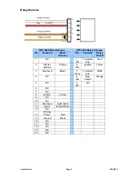
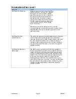
Main Harness Connections in Detail
RED (+) Constant 12volt Input
Locate the Red wire found on the 20-pin connector supplied with the GPS unit.
The red wire must be connected to a constant 12-volt source from the vehicle to
power the GPS unit. It's important that the 12 volt power source maintains 12
volts at all times.
BLACK (-) Chassis Ground Input
Locate the Black wire found on the 20-pin connector supplied with the GPS unit.
The black wire must be connected to a solid chassis ground uninhibited by paint
or plastics. It is important that you do not use any floating grounds from the
vehicles electrical system. Always connect the ground directly to the chassis
body and secure with a factory bolt or aftermarket screw insuring wire to metal
connection.
YELLOW (+) Ignition Input
Locate the yellow wire found on the 20-pin connector supplied with GPS unit.
The yellow wire must be connected to a true ignition12-volt source from the
vehicle. This connection is used to monitor the engines on/off state. It's important
that the switched 12-volt source is (0) zero when the engine is off and switched
12 volts with the engine cranking and running.
WARNING:
Yellow wire must be
connected for the GPS receiver to work properly!
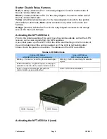
Orange (-) Starter Disable Output
This output will connect directly to the orange wire on the starter relay harness.
Locate the orange wire found on the 20-pin connector supplied with the GPS
unit. This output will only be triggered when a command is sent to disable the
starter.
BROWN/WHITE (-) Input
This alarm input requires a rest at 12v switch to ground constant trigger 15
seconds long (no pulse). Locate the brown/white wire found on the 20-pin
connector supplied with the GPS unit. The brown/white wire should be connected
to a constant trigger circuit, such as siren output.
NOTE:
Yellow wire must see
12v on and off before testing for the first time.