background image

Chapter 8: 

Main Toolbar Features 


VSP User Manual 

55


Version 1.7.92 

 
I (xx, yy, zz)

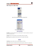
: shows the calculated moment of inertias in the X, Y and Z direction. 

 
I (xy, xz, yz):

 shows the cross products of the moments of inertia. 


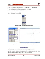
Aero Reference (Aero Ref) 


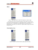
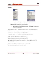
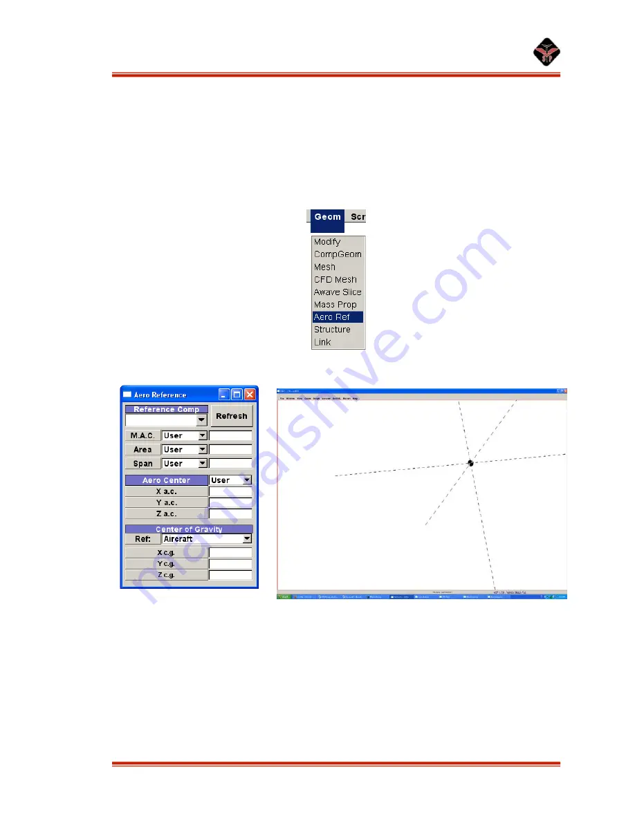
Figure 51: Aero Reference option under Geometry Menu 


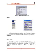
Figure 52: Aero Reference Window (left) and Coordinate System (right) 


Reference Comp 

 
Reference Comp

: select a specific component using the drop down menu. 

 
Refresh: 

updates the visual location in the window for the aerodynamic center and center 

of gravity depending upon the specify reference component picked. 

Summary of Contents for Vehicle Sketch Pad

Page 1: ...User Manual Vehicle Sketch Pad Version 1 7 92...

Page 2: ...tact Mark Moore Aeronautics Systems Analysis Branch Mail Stop 442 1 North Dryden St NASA Langley Research Center Hampton VA 23681 0001 OpenVSP is a parametric aircraft geometry tool OpenVSP allows the...

Page 3: ...Parts 11 General Parameters Gen Tab 11 Cross Section Formation XForm Tab 13 Chapter 3 Designing a Pod Design tab 15 Chapter 4 Designing Wings All Wings 16 Planform Plan Tab 16 Foil Tab 17 Multi Secti...

Page 4: ...ab 37 Inlet tab 39 Chapter 8 Main Toolbar Features File Menu 41 Insert 41 Import 41 Export 41 Window Menu 42 Window Split 42 Background Picture 42 Lighting 43 Labels 44 View Menu 44 Preset Views 44 Ad...

Page 5: ...Input 2 Tab 67 Slice Tab 69 Control Tab 71 Execute Tab 72 Revert 74 Help 74 About 74 Chapter 9 Modeling Example Wing 75 Tails 75 Fuselage Layout 76 Editing Cross Sections 76 Prop 77 Landing Gear 78 Fi...

Page 6: ...ile Extension Vehicle Sketch Pad uses the XML extension for its files VSP can read RAM files however the XML extension should be used if files are to be edited Saving Files Figure 1 Save options under...

Page 7: ...naged next to Show by using the drop down menu For this example only af file extensions will be shown This will help to condense the amount of information that appears in the main window In order to s...

Page 8: ...part from the drop down list at the top of the Geom Browser Window then click Add Delete a Part Select Part from Part list then click Cut Modify a Part Select Part from Part List The Part Window will...

Page 9: ...ranslates the model around the screen View Keys The Function Keys at the top of the key board are for preset views F1 through F4 are user defined views To set a user defined view adjust the model on t...

Page 10: ...low shows the Geom window and the list of available parts Figure 4 Geom window and list of available parts The selected part will appear in the Main Screen and the Part Window will open The Part Windo...

Page 11: ...to feet or meters etc All units for aspects such as length width chord etc are given only as relative scalars This feature allows designers to quickly model aircraft without worrying about conversion...

Page 12: ...e Transforms pane of the XForm tab click Rel Relative Now in the Gen tab select the UV box Note that V measures the child part s attachment from the trailing edge of the wing Adjusting the U slider mo...

Page 13: ...ly identify the part that is being created The name chosen is what the part will export as Some other programs into which parts may be imported may only look for these specific names when attempting t...

Page 14: ...aced 0 0 being the leading edge and 1 0 being the trailing edge Symmetry This allows users to modify the part quickly without having to do the same work twice Choose the symmetry about the plane on wh...

Page 15: ...al 15 Version 1 7 92 Chapter 3 Designing a Pod Design tab The design tab specifically for a pod is shown below Figure 7 Pod Design tab Length Set the length of the pod Fine Ratio Set the fineness rati...

Page 16: ...re three tabs that are common between all wing type browsers Plan Sect and Foil These three are explained below and the ones unique to each type are explained in separate sections Planform Plan Tab Th...

Page 17: ...he drop down box and changing the Camber Camber Loc and Thick sliders will change the name of the NACA airfoil that is displayed in this field This allows designers to see which airfoil name correspon...

Page 18: ...Designing Wings VSP User Manual 18 Version 1 7 92 Figure 9 Multi section Wing Foil tab Multi Section MS Wings Section Sect Tab The section tab for an MS Wing is shown below Figure 10 Multi section Win...

Page 19: ...out of the six parameters to define the specific wing section The user must select which of the six slider bars become available For instance selecting Span TC RC will allow the user to change the Spa...

Page 20: ...g 360 to 360 degrees Figure 11 Multi section Wing Dihedral tab Blend Attach Points Attach 1 Choose what percentage of the interior part that will attempt to blend with the exterior side of the joint 0...

Page 21: ...the cross sections are slanted to give the wing a smoother look Hybrid Wing Bodies HWB Section Sect Tab The section tab for a HWB is shown below The section tab is very similar to the one for a MS Win...

Page 22: ...ween sections 1 degree is very smooth 30 degrees is less smooth This is the angle of each segment added 5 degree sweep per segment 10 degree sweep per segment etc Sweep Fillets Span 1 Blends the two s...

Page 23: ...Dihedral Fillets Span Tip Blends the dihedral angles of the two sections together creates a smooth curve between the two Change to a front or rear view to observe these changes Interpolation Control...

Page 24: ...tting the numbers next to the sliders 4 Set the sweeps of each section to zero 5 Access Section 1 and set the Span to 4 0 6 Go into the Dihed tab There are 2 joints 0 and 1 7 Select Joint 0 using the...

Page 25: ...k like a cylinder 6 Go to the Sect tab and Insert six more sections each with a span of 0 2 a Click Insert once and the Total Num Secs box should display 2 b Access Section 1 and change the span to 0...

Page 26: ...rotated and moved to suit in the XForm tab The lengths of the various sections can be adjusted by changing their spans in the Sect tab Add more turns and whatever else is needed to finish the pipe An...

Page 27: ...e the basic qualities of the fuselage Note The more cross sections one adds the better the camber adjustment will be Inner Mold Line Definition Inner Mold Line IML is primarily used for jet transports...

Page 28: ...ss section constant so the wall thickness might not always be constant The Modify variable beneath the Wall Thickness sliders allows the user to modify either the Inner Mold Line IML or Outer Mold Lin...

Page 29: ...st the cross sections on both sides of the cross section selected Num 1 2 Adjusts the cross sections on only one side Cross Section XSec Tab This tab is the most important of the available fuselage op...

Page 30: ...igure 18 Fuselage Cross Sections tab Type The user can select the type of cross section to use Note Also one can read in a fuselage file fxs Graph The picture in the bottom of the window shows the cur...

Page 31: ...imported into that particular code To find what each adjustment does refer to the code s definitions Modifications The HAVOC part has 3 unique tabs that have many different features that can be adjus...

Page 32: ...Store part will create two external stores each time the user adds this part to the design To add only one external store at a time select the XForm tab and select None from the Symmetry drop down box...

Page 33: ...to a flat plate at 90 deg angle of attack with a similar frontal area same as that which is under the Type part of this section Blank Definition A Blank component is added as the ultimate parent in th...

Page 34: ...Chapter 7 Additional Parts VSP User Manual 34 Version 1 7 92 Figure 21 Duct Shape tab Foil Tab Figure 22 Duct Foil tab The Foil tab is identical to the MS Wing s Foil tab...

Page 35: ...diameter cone angle and blade pitch to be set The Blade Pitch rotates all of the propeller s blades at the same time Num U and Num W This adjusts the number of radial U and spanwise W sections of eac...

Page 36: ...e blade are adjusted Station This is similar to the Sect ID and Joint ID of the MS Wing Sect and Dihed tabs Each station denotes a different portion of the propeller Location This specifies the locati...

Page 37: ...e Foil tabs of the MS Wing and HWB parts Engine Definition This feature is a pre built jet engine One can add an S Duct like on a L1011 or B727 center engine or like many fighter aircraft Engine Eng N...

Page 38: ...Hub RTip The ratio of the bullet size to the fan size Max RTip The ratio of the outside cowling dimensions to the fan radius Len RTip The ratio of engine length to the fan radius Nozzle Parameters Le...

Page 39: ...rom the centerline of the engine Shape Adjust the Shape to change the turn of the inlet Note In order to offset the inlet in different directions in the YZ plane use X Rot under the X Form tab Inlet t...

Page 40: ...xis the throat is located H W Adjusts the diameter of the cowling Note if the H W is set to a value other than 1 turn on the duct option otherwise a discontinuity will appear in the cowling Shape Fact...

Page 41: ...child parts will move and or rotate with it The rotation point is about the origin of the file in which parts were assembled After the parts are inserted the Attach Matrix button in the Gen tab is sel...

Page 42: ...ay be used as background pictures To set the background picture select the Main Window and click the Window menu Select Background after which another menu appears The background color can be selected...

Page 43: ...ht boxes that are selected the more brightly lit the model will be The user may choose from three variables to control the light Ambient Amb This slider controls the intensity of the selected lights f...

Page 44: ...ay on the main window even when no objects are present Note The dimensions and text are cut if the points to which they are attached are cut but the labels do not copy and paste Once the points are cu...

Page 45: ...rrent airplane with a picture of the aircraft set as the background picture When using the mouse it is difficult to line up the model exactly To remedy this select Adjust from the View menu and use th...

Page 46: ...it can be recognized if later adjustments are needed Position Move texture laterally U and longitudinally W Scale Adjust the size of the texture laterally U and longitudinally W Bright Adjust the bri...

Page 47: ...on under the Geometry menu The Component Geometry is a tool that calculates the areas and volumes of all the parts in the model It also creates a mesh of the model This command writes a file to the di...

Page 48: ...The mesh is of low quality and is not recommended for use in CFD The mesh is applicable for stereo lithography CFD Mesh The meshing code will intersect trim and mesh VSP models based on user defined g...

Page 49: ...ng process This panel is accessed from the Geom menu under CFD Mesh Max Edge Len Target edge length all triangles not covered by sources Adjust Len Adjust the target length of all sources Adjust Rad A...

Page 50: ...s a mesh on a single component Mesh All places a mesh on all the components Export Final Mesh exports a real mesh that is accurate and water tight for CFD analysis The file is exported as a NASCART GT...

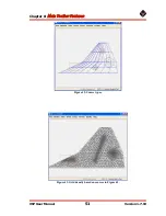
Page 51: ...Chapter 8 Main Toolbar Features VSP User Manual 51 Version 1 7 92 Figure 42 Source types Figure 43 Grid density based on sources in Figure 42...

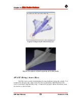
Page 52: ...esh approximately 250 000 triangles AWAVE Slicing Awave Slice The Slice tool is useful in determining the area distribution along the aircraft For example the designer may want to have the cross secti...

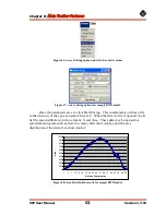
Page 53: ...rectory of the vsp exe named slice txt When the slice txt file is opened it will list the area distribution in two columns X and Area These data may be ported to a spreadsheet program such as Excel to...

Page 54: ...specify the number of slices in the model The more slices there are the more accurate the results will be Compute Click to obtain results once the number of slices is specified Draw Cg places a graphi...

Page 55: ...nts of inertia Aero Reference Aero Ref Figure 51 Aero Reference option under Geometry Menu Figure 52 Aero Reference Window left and Coordinate System right Reference Comp Reference Comp select a speci...

Page 56: ...y of the model in the X Y and Z direction Structural Modeling Figure 53 The Structure option under the Geometry menu Currently only multi section wings are supported for structural modeling The code a...

Page 57: ...tures VSP User Manual 57 Version 1 7 92 Figure 54 Multi Section Wing Figure 54 displays the multi section wing used in this example To add structural components select Geom Structure from the menu Fig...

Page 58: ...kin thickness Splice Line ID Choose which splice line to edit Splice Line Loc Location of line as a percentage of span per section Splices Thickness definition points Add Splice Press this button to a...

Page 59: ...this section Delete Spar Delete the current red spar Thickness Set spar thickness Density Set spar material density Position Set spar position percent span for this section Sweep Abs Sweep absolute fr...

Page 60: ...FEA Mesh button Several files are exported after the meshing is completed feageom dat The mesh geometry for Calculix 6 node triangles and 8 node quads feanodethick dat Thickness of each node for Calcu...

Page 61: ...ARY NFIXED 1 3 MATERIAL NAME AL ELASTIC 70000 0 0 33 20 0 DENSITY 1 894e 9 SHELL SECTION ELSET Eallquads MATERIAL AL 0 05 SHELL SECTION ELSET Ealltris MATERIAL AL 0 05 INCLUDE INPUT feanodethick dat S...

Page 62: ...consider if a engine is linked with the fuselage with respect to length at a certain distance along the fuselage from the end If the length of the fuselage is changed the engine will stay at that spe...

Page 63: ...run in Vorlax Card 2 Solution LAX chordwise or steamwise spacing of vortices Setting this to 0 is cosine spacing and setting the value to 1 is equal spacing HAG Height above ground for ground effect...

Page 64: ...0 1 1 0 0 2 2 0 0 3 3 0 0 4 4 0 Note Do not try to perform the Neutral Point analysis IAC 1 with ISWEEP 1 because the calculations do not work out correctly ITRMAX Maximum number of Gauss Seidell Iter...

Page 65: ...ic flight and configuration When the value is 1 it symbolizes asymmetric flight and or configuration PSI Sideslip angle in units of degrees PITCHQ Pitch rate in units of degrees second Positive pitch...

Page 66: ...CDO the parasitic drag coefficient which is based on drag due to zero lift Card 9 IBURST a value of 1 will turn on the Vortex Burst model XREF the location in x of the start of the vortex ANGCRT the...

Page 67: ...e default value is 0 0001 Input 2 Tab Card 3 Mach Numbers NMACH Number of Mach numbers to be analyzed XMACH NMACH number of Mach numbers Card 4 Alpha Numbers NALPHA Number of angle of attacks to be an...

Page 68: ...ue of 1 this is the desired CL The default value is zero This is also an array of NTRIM points CMTRIM for ITRIM with a value of 1 or 2 this is the desired Cm The default value is zero and it is also a...

Page 69: ...NUMREN number of Reynolds numbers in Mach Re Cl Cd table NUMMCH number of Mach numbers in Mach Re Cl Cd table Slice Tab Auto Slice Auto Find places a key slice wherever a slope discontinuity in the sh...

Page 70: ...ce with be outlined in bright red Y slider allows for the location of the enabled slice to be adjusted along the Y direction Add locks the enabled key slice into position Symmetry will place a key sli...

Page 71: ...will update the number of interpolated slices in steps of 1 and the double arrow buttons will update the number of interpolated slices in steps of 5 Delete deletes whichever key slice is shown next to...

Page 72: ...e a specific control surface from the list Add Delete Control Surfaces Trap Number use the arrow buttons to access a specific trapezoid as denoted by the Interpolated slices Add Del Control Surf click...

Page 73: ...ace Slices displays the key slices on the cross section surface Camber shows the camber on the cross section surface The wheel next to Scale controls the size of the camber Turn Off All hides the Xsec...

Page 74: ...again activated in the Geom Browser the Revert option will undo changes made past that point In order to ensure that you do not accidently deactivate the part and be unable to undo your changes save...

Page 75: ...background It may be advisable to resave the top view in order to line it up again after changing the wing A sample of the wing layout is shown below Figure 70 Top view of Cessna 210 and initial VSP...

Page 76: ...of the part over the nose in the background image It should now be the proper length and in the proper location Editing Cross Sections It is now time to edit the cross sections of the fuselage in ord...

Page 77: ...o the first method is that the transition between the pieces is smooth because it is all the same part in VSP The advantage to the second is that all of the taper ratios can be used more than once The...

Page 78: ...te the second cross section at 65 Now do a Z Rot of 90 degrees and the result will be a nice tire twelve inches in diameter Struts are also just fuselages Set the cross sections to circles and move th...

Page 79: ...section out to the ends to form a cylinder Then change the color to make it stand out Name it Measuring Stick for example Then adjust the length to exact between the spots to be measured and read the...

Page 80: ...Browser window click Cut select the parent part and click Paste The new child part should be shifted over by 2 minus signs to show the relationship Then in the child s Part Menu under the Gen tab one...

Page 81: ...elationship where the child s location follows a point on the surface of the parent Note this point can be adjusted with the sliders and or the number box to the right of the button Wire View This vie...

Reviews: