background image

OPERATION

OPERATION

OPERATION

OPERATION

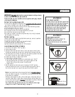
CAUTION

 : 

 Avoid inhaling fumes emitted from the heater's 

first use. Smoke and odor from the burning of oils used in 

manufacturing will appear. Both smoke  and odor will 

dissipate after approximately 30 minutes. The heater 

should NOT produce thick black smoke.

"

O W

NOTE:

When heater is ON:

"

O W

The burner may be noisy when initially turned on. To eliminate excessive
noise from the burner, turn the Control Knob to the   LOW   position. Then, 
turn the knob to the level of heat desired.

Emitter screen will become bright red due to intense heat. The color is more 
visible at night. Burner will display tongues of blue flame. These flames 
should not be yellow or produce thick black smoke, indicating an obstruction
of airflow through the burners.

RELIGHT

1)Turn the control knob to  OFF   position.
2)Wait five (5) minutes before attempting to relight pilot.
3) Repeat steps beginning with step 2  above.

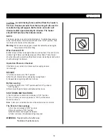
SHUT DOWN INSTRUCTIONS

1) Push in and turn control knob clockwise to "OFF" position.
2) Turn L.P. tank  gas  valve clockwise to  "OFF" position when 
heater is not in use

WARNING  

:Heater will be hot after use. 

Handle with extreme care.

Pus

h to

 tu

rn

OFF

H

GI

H

LO

W

TO

LI

P

Pus

h to

  tu

rn

OFF

H

GI

H

LO

W

TO

LI

P

The Event of Gas Leakage

"

O W

2)Turn LP cylinder to  OFF  position.
3)Wait 5 minutes to allow gas to dissipate.
4)If odor continues, immediately call gas supplier.

"

O W

1)Turn the control knob to  OFF   position.

If the flame is very small, this  is because the supply pressure 
is not enough.

Operation Pressure Checked

1)Turn the control knob to "OFF" position and Turn LP cylinder to 
    "OFF" position.
2)Never leave the patio heater unattended while in use.

Before Leaving

12

Note

:   After use, some discoloration of the emitter screen is normal.

Warning:

 White smoke may appear around the radiant head during the

                   first minutes of the initial firing.  

Summary of Contents for PTH38PCP

Page 1: ...ny open flame 3 if odor continues immediately call gas supplier FOR YOUR SAFETY Do not store or use gasoline or other flammable vapors or liquids in the vicinity of this or any other appliance WARNING For Outdoor Use Only CAUTION Retain the instructions for future use PTH38PSS CERTIFIED I S G E N D C D E E R I T F I PTH38PCP PTH38PGM ...

Page 2: ... marked in accordance with US DOT specifications The unit should be secured or moved indoors if winds exceed 35 km h Storage indoors is permissible only if the cylinder is removed WARNING Improper installation adjustment alteration services or maintenance can cause injury death or property damage Read the installation operating and maintenance instructions thoroughly before installing or servicing...

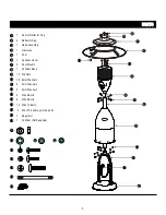
Page 3: ...Assembly 1 Gas Hose 1 Post 1 Cylinder Cover 1 Cylinder Base 15 M6 Nuts 18 6mm Washers 5 M4 8 Bolts x 3 Post Mounts 10 12 1 Center Reflector Cap 12 M6 10 Bolts x 13 15 16 3 M6 x70 double pointed bolts 14 5 4mm Washers 12 13 9 17 16 6 M5 8 Bolts x 18 6 5mm Washers 11 14 2 4 5 7 6 3 1 8 14 16 17 10 9 15 13 ...

Page 4: ... a qualified service person The heater should be inspected before use and cleaning may be required at least once a year or as necessary It is imperative that control compartment burner and circulating air passageways of the heater be kept clean Keep the appliance area clear of combustible materials such as gasoline and other flammable vapors and liquids Do not obstruct the flow of combustion and v...

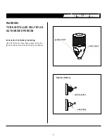
Page 5: ...O BE INSTALLED ONLY BY AN AUTHORISED PERSON Instruction For Battery Installing Upon first time use of the product please remove the ignition button and install an AAA battery as indicated Ignition button Replace Battery Control knob Ignition button AAA battery 5 ...

Page 6: ...per assembly is the responsibility of the installer Step 1 Step 1 Step 2 Step 2 M5 X 8 bolts 6 pcs and 5mm washers 6 pcs Attach the post to the post mounts using Attach Post to Base Assembly 7 Attach Cylinder Cover to Post Mounts Attach the cylinder cover to the post mounts 7 6 14 11 5 ...

Page 7: ...ly to Post Load head assembly by inserting gas hose into post Insert head assembly into post Tighten securely using M4 X 8 Bolts 5 pcs and 4mm washers 5 pcs Step4 Attach Double Pointed Bolt to Attach M6 X 70 double pointed bolts 3 pcs and 6mm washers 3 pcs to the top of head assembly and tighten the bolts securely Head Assembly Step 3 Step 4 3 5 3 13 16 10 12 4 ...

Page 8: ...12 pcs Step 6 Attach Center Reflector and Reflector Load center reflector and reflector to the top of head assembly by M6 X 70 double pointed bolts 3 pcs to the top of Head Assembly 6mm washers 3 pcs and nuts 3 pcs 10 9 8 NOTE Assembly of this heater requires basic mechanical skills Proper assembly is the responsibility of the installer ASSEMBLY ASSEMBLY Step 6 3 10 9 ...

Page 9: ...ly Move cylinder to the plate of base assembly Your Patio Heater has been checked at all factory connections for leaks To check the Connection of the gas hose regulator cylinder 1 Make leak solution by mixing 1part liquid dish soap and 3 parts water 2 Spoon several drops or use squirt bottle of the solution onto the gas hose regulator and regulator cylinder connection 3 Inspect the connections and...

Page 10: ...p 9 6 8 WARNING TO BE INSTALLED ONLY BY A COMPETENT PERSON Step 10 Step 10 6 Disconnect Cylinder When Storing or Transporting 7 1 Turn off the heater 2 Upper the cylinder cover onto the post mounts 3 Turn off the valve of the cylinder 4 Loosen the screw of cylinder and regulator 5 Disconnect the cylinder from regulator ...

Page 11: ... minutes after use Allow emitter and dome to cool before touching 1 Turn the control knob to OFF position 2 Fully open gas valve 3 Depress control knob and turn knob counter clockwise to PILOT whilst simultaneously pressing the electronic ignition button until light the pilot 4 Once the pilot is lit continue to keep the control knob depressed for at least 30 seconds After 30 seconds release contro...

Page 12: ... minutes before attempting to relight pilot 3 Repeat steps beginning with step 2 above SHUT DOWN INSTRUCTIONS 1 Push in and turn control knob clockwise to OFF position 2 Turn L P tank gas valve clockwise to OFF position when heater is not in use WARNING Heater will be hot after use Handle with extreme care P u s h t o t u r n OFF H G I H L O W T O L I P P u s h t o t u r n OFF H G I H L O W T O L ...

Page 13: ...ust conform to local codes or in the absence of local codes with the standard for the storage and handling of liquid petroleum gases ANSI NFPA 58 1986 or most recent addition For Canada with the current CAN1 B149 This heater must be placed on level firm ground Never operate in an explosive atmosphere Keep away from areas where gasoline or other flammable liquids or vapors are stored or used BE CAR...

Page 14: ...rbon deposits develop WARNING DO NOT touch or move heater for at least 45 minutes after use Allow all burner elements to cool before touching FOR YOUR SAFETY NOTE In a salt air environment such as near an ocean corrosion occurs more quickly than normal Frequently check for corroded areas and repair them promptly STORAGE Between uses During periods of extended inactivity or when transporting NOTE W...

Page 15: ...onnection Tighten connection Thermocouple bad Replace Thermocouple Gas leak in line Check connections Burner will not light Pressure is low Fuel tank is near empty Orifice blocked Remove clean and replace Control Valve not ON Turn valve to ON Thermocouple bad Replace Thermocouple Pilot light assembly bent Place pilot in proper or not in correct location position and retry Fuel Tank empty Refill LP...

Reviews: