background image

W415-2339 / C / 02.08.21

EN

18


venting

2.9  vertical through existing chimney

!

WARNING

•  Risk of fi re.

•  Co-axial to co-linear venting confi gurations must only be used in a non-combustible chimney or enclosure. 

Installation in a combustible enclosure could result in a fi re.

This appliance is designed to be attached to a 3” (76.2mm) co-linear aluminum fl ex vent system running the full 

length of a masonry chimney.

The fl ex liners accommodate any contours of a 

masonry chimney, however, it is necessary to keep 

the fl exible liners as straight as possible. The inlet 

air collar of the termination cap must be connected 

to the air intake fl ex liner and the exhaust collar 

must be connected to the exhaust fl exible liner.

Both Simpson Duravent and Selkirk co-linear to 

co-axial adaptors have been approved on this 

appliance 

Follow vent manufacturer’s installation instructions. 

Different manufacturer’s venting 

components must not be combined. 

Once the preferred manufacturer’s 

appliance adaptor has been attached, the 

remainder of the system must be that of 

the same manufacturer.

The only exception to this rule is to use 

Wolf Steel’s approved 3” (76.2mm) fl ex 

liner and co-linear termination.

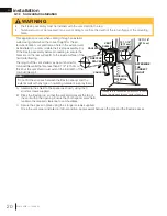
AIR

INTAKE

EXHAUST 

FLUE

FLEX

LINER

*

 40 FT (12.2m)

MAX.

10 FT (3.1m)

MIN

COAXIAL TO 

CO-LINEAR 

ADAPATOR

APPLIANCE

VENT ADAPTOR

TERMINATION

* Measured from appliance fl ue collar 

to termination fl ue collar

note:

A vent adaptor will be required directly off the appliance.

Summary of Contents for Haliburton GDS28-1NE

Page 1: ...rom a neighbour s phone Follow the gas supplier s instructions If you cannot reach your gas supplier call the fire department Installation and service must be performed by a qualified installer servic...

Page 2: ...burns A physical barrier is recommended if there are at risk individuals in the house To restrict access to an appliance or stove install an adjustable safety gate to keep toddlers young children and...

Page 3: ...ease anemia those under the influence of alcohol those at high altitudes are more affected by carbon monoxide than others Failure to keep the primary air opening s of the burner s clean may result in...

Page 4: ...tion 21 horizontal air terminal installation model GDS28 21 vertical air terminal installation 22 appliance vent connection 23 natural vent specifics 23 chimney installation 23 combustion air 23 insta...

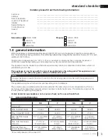
Page 5: ...ted This appliance may be installed in an aftermarket permanently located manufactured mobile home where not prohibited by local codes This appliance is only for use with the type of gas indicated on...

Page 6: ...athroom unless the unit is a direct vent sealed combustion product The installation must conform with local codes or in absence of local codes the National Gas and Propane Installation Code CSA B149 1...

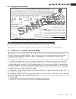
Page 7: ...sceller l vacuation apr s avoir executer l entretien du syst me de prise d air Serial Number N de S rie W385 XXXX REFERENCE 161746 XXXX VENTED DECORATIVE GAS APPLIANCE NOT A SOURCE OF HEAT NOT INTENDE...

Page 8: ...on GAS LINE ACCESS HOLE LOCATED IN PEDESTAL BASE 26 3 4 680mm 22 1 2 572mm 11 1 4 286mm 7 178mm AIR INTAKE 10 254mm 12 305mm 17 3 4 451mm 18 1 2 470mm 5 1 2 127mm 4 102mm FLUE SAFETY BARRIER 1 3 4 44m...

Page 9: ...110 8 12 to 12 12 roof terminal kit GD 111 flat roof terminal kit GD 112 or periscope kit GD 180 for wall penetration below grade in conjunction with the appropriate venting components A terminal sha...

Page 10: ...er start up and or carboning Use an adjustable pipe as the final length of rigid piping to the stove for ease of installation These vent kits allow for either horizontal or vertical venting of the app...

Page 11: ...12 305mm above grade The maximum allowable vent length including both rise and run is 10 3m for a fireplace and 8 2m for a stove An insulation sleeve is illustrated in the top vent image below use onl...

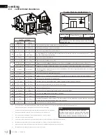
Page 12: ...ang N 16 40 6cm 16 40 6cm Clearance above the roof O 2 0 6m 2 0 6m Clearance from an adjacent wall including neighbouring buildings P 8 2 4m 8 2 4m Roof must be non combustible without openings Q 3 0...

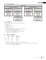
Page 13: ...of 40 feet 12 2m Horizontal run vertical rise to maximum of 40 feet 12 2m Vertical Termination For the following symbols used in the venting calculations and examples are greater than equal to or gre...

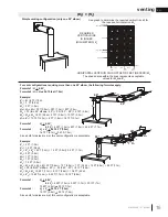
Page 14: ...0 9m V2 8 FT 2 4m VT V1 V2 3 FT 0 9m 8 FT 2 4m 11 FT 3 4m H1 2 5 FT 0 8m H2 2 FT 0 6m HR H1 H2 2 5 FT 0 8m 2 FT 0 6m 4 5 FT 1 4m HO 03 three 90 elbows 90 03 270 90 5 4 FT 1 7m HT HR HO 4 5 FT 1 4m 5 4...

Page 15: ...8m 16 7FT 5 1m Formula 1 HT 4 2 VT 4 2 VT 4 2FT 1 3m x 6FT 1 8m 25 2 FT 7 7m Formula 2 HT VT 24 75 FT 7 5m 16 7 FT 5 1m 24 75 7 5m Since both formulas are met this vent configuration is acceptable 90...

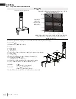
Page 16: ...ple V1 5 FT 1 5m V2 6 FT 1 8m V3 10 FT 3 1m VT V1 V2 V3 5FT 1 5m 6FT 1 8m 10FT 3 1m 21FT 6 4m H1 8 FT 2 4m H2 2 5 FT 0 8m HR H1 H2 8FT 2 4m 2 5FT 0 8m 10 5 FT 3 2m HO 03 four 90 elbows 90 03 360 90 8...

Page 17: ...HR H1 H2 6FT 1 8m 2FT 0 6m 8 FT 2 4m HO 03 four 90 elbows 90 03 360 90 8 1 FT 2 5m HT HR HO 8FT 2 4m 8 1FT 2 5m 16 1FT 4 9m HT VT 16 1FT 4 9m 4 5FT 1 4m 20 6 FT 6 3m Formula 1 HT 3VT 3VT 3FT 0 9m x 4...

Page 18: ...ntake flex liner and the exhaust collar must be connected to the exhaust flexible liner Both Simpson Duravent and Selkirk co linear to co axial adaptors have been approved on this appliance Follow ven...

Page 19: ...take vent pipe joints must be sealed using red RTV high temp silicone sealant W573 0002 not supplied or black high temp Mill Pac W573 0007 not supplied If using pipe clamps to connect rigid vent compo...

Page 20: ...irestop top so that the vent shield covers the top of the vent within the opening Ensure that both spacer and shield maintain the required clearance to combustibles C Secure the spacer in place using...

Page 21: ...ld and tighten This will prevent any materials such as insulation from filling up the 1 25mm air space around the pipe Caulking Vent Pipe Shield Vent Pipe Shield Vent Pipe Collar Firestop underside of...

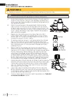
Page 22: ...over the air terminal connector leaving a min 3 4 19mm of the air terminal connector showing above the top of the flashing Slide the flashing underneath the sides and upper edge of the shingles Ensure...

Page 23: ...ible on the exterior pipes once installation is completed An optional decorative black band may be available with this appliance In the event that the venting must be disassembled care must be taken t...

Page 24: ...insert the protective bushing Pull both spill switch wires through the bushing taking up any slack Replace the cover plate FOR MILLIVOLT Disconnect one of the black on off switch wires and attach to...

Page 25: ...the chimney extends more than 5ft 1 5m above the roof it must be secured using a roof brace or guide wires A raincap must be installed to avoid internal damage and corrosion 3 FT 1m MIN 3 FT 1m MIN 1...

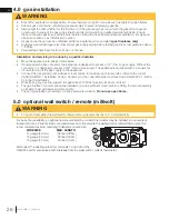
Page 26: ...nce is equipped with a manual shut off valve to turn off the gas supply to the appliance Connect the gas supply in accordance to local codes In the absence of local codes install to the current CAN CS...

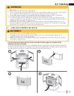
Page 27: ...slam or scratch Do not operate appliance with glass removed cracked or scratched Facing and or finishing material must never overhang into the appliance opening The glass door assembly is a safety de...

Page 28: ...frame Snap the rear handle hook to lock the latch closed To open the door repeat in reverse order HINGE PIN BUSHING CATCH SLOT DOOR LATCH WARNING Glass may be hot Do not touch glass until cooled If eq...

Page 29: ...uring process 1 3 4 Fig 1 WARNING Failure to position the logs in accordance with these diagrams or failure to use only logs specifically approved with this appliance may result in property damage or...

Page 30: ...ed to direct flame Use only certified glowing embers and PHAZER logs available from your local authorized dealer distributor WARNING Completely blocking the burner ports can cause an incorrect flame p...

Page 31: ...ated above the spill switch bracket on the adaptor D Venting action is satisfactory if the flame stays lit Venting action is unsatisfactory if the flame extinguishes E If venting action is unsatisfact...

Page 32: ...efore using the appliance Place near the IPI board If the back up is used it must be connected to this 6 volt battery pack supplied Do not connect to a 9 volt battery pack note PILOT W725 0062 NG W725...

Page 33: ...d I Turn on the remote wall switch to the appliance J If the appliance will not operate follow instructions TO TURN OFF GAS and call your service technician or gas supplier A Set thermostat to lowest...

Page 34: ...ll then begin the countdown for approximately seven days before shutting off the pilot if the appliance is not used This countdown will reset anytime the appliance main burner is used Therefore if the...

Page 35: ...t continue to burn repeat steps E through I J With pilot lit turn gas knob counter clockwise to the ON position K If equipped with the flame adjustment valve push and turn the knob to high L Turn on a...

Page 36: ...ith a soap and water solution Prior to pilot adjustment ensure that the pilot assembly has not been painted If overspray or painting of the pilot assembly has occurred remove the paint from the pilot...

Page 37: ...fting from the burner ports The flame may not appear yellow immediately allow 15 to 30 minutes for the final flame colour to be established AIR SHUTTER ADJUSTMENT MUST ONLY BE DONE BY A QUALIFIED INST...

Page 38: ...r 5 If your appliance is equipped with a safety barrier cleaning may be necessary due to excessive lint dust from carpeting pets etc simply vacuum using the brush attachment 6 If your appliance is equ...

Page 39: ...ld be performed by a qualified service technician The firebox becomes very hot during operation Let the appliance cool completely or wear heat resistant gloves before conducting service Never vacuum h...

Page 40: ...are neither pinched nor interfere with the blower operation Re secure the air intake manifolds INSTALLATION THROUGH THE FIREBOX REPLACEMENT BLOWER ACCESS GASKET IS REQUIRED Turn off the electrical pow...

Page 41: ...replacement parts a photocopy of the original invoice will be required to honour the claim When ordering replacement parts always give the following information Model Serial Number of appliance Instal...

Page 42: ...GL 620 Left side log GL 620 W550 0001 W135 0061 12 13 11 10 5 6 7 8 9 Yes Glowing embers GL 620 W361 0016 Yes Yes ON OFF switch W660 0009 Trivet W010 2511 Yes Right side log GL 620 W135 0060 W715 0059...

Page 43: ...100 0056 Main burner assembly W680 0008 Thermocouple Stocked Stocked Yes W010 0633 Pilot assembly NG w ignitor W290 0029 Pilot gasket W725 0042 Valve NG Yes Yes 14 14 14 14 14 14 14 14 14 12 13 14 14...

Page 44: ...rifice 54 P W456 0040 Burner orifice 40 NG W100 0056 Main burner assembly W455 0070 Pilot orifice 62 NG Stocked Stocked Yes W010 2763 Pilot assembly NG W290 0029 Pilot gasket W725 0062 Valve NG Yes Ye...

Page 45: ...fety barrier assembly 1 Stocked 23 23 23 5 23 4 23 3 23 1 7 6 23 2 23 8 AR28SS W660 0081 Wall mounted thermostat F45 F60 Hand held remote control 6 3 3 GS328SSB Satin chrome plated door GS328KSB Metal...

Page 46: ...heck that main burner is operating on HI AFTER TAKING PRESSURE READINGS BE SURE TO TURN SCREWS CLOCKWISE FIRMLY TO RESEAL DO NOT OVER TORQUE Leak test with a soap and water solution Air shutter improp...

Page 47: ...ple Clean thermocouple and valve connection Replace thermocouple Replace valve Faulty valve Replace Pilot burning no gas to main burner gas knob is on HI wall switch thermostat is on Thermostat or swi...

Page 48: ...rting or faulty Loosen and tighten thermocouple Clean thermocouple and valve connection Replace thermocouple Main burner goes out pilot stays on Venting is spilling Test with spill switch bypassed Che...

Page 49: ...al DO NOT OVER TORQUE Leak test with a soap and water solution Air shutter improperly adjusted Return air shutter to specified opening see venturi adjustments section in the installation manual Carbon...

Page 50: ...nded Receiver if equipped Reset program hold reset button on receiver and wait for 2 beeps Release after second beep Press small flame button on remote within 20 seconds you will hear an additional be...

Page 51: ...ose one of the 3 methods below to reset the system 1 To reset ignition box when locked out Turn off power supply and remove batteries if used from the back up battery pack 2 To reset the DFC Board whe...

Page 52: ...caused by mechanical systems such as exhaust fans furnaces clothes dryers etc Any damages to the appliance combustion chamber heat exchanger plated trim or other components due to water weather damag...

Page 53: ...C 02 08 21 53 service history 18 0 service history Appliance Service History This appliance must be serviced annually depending on usage Date Dealer Name Service Technician Name Service Performed Spec...

Page 54: ...P P P P P P P PO O O O O O OL L L L L L L LE E E E E EO O O O O ON N N N C C C CE E EL L LE E EB BR RA AT TI IN NG G O OV VE ER R 4 40 0 Y YE EA AR RS S A A A O O O O O OF F F F F F H H H H H H H HO O...

Reviews: