background image

17

W415-0379 / E / 04.24.12

D. 

Place the bottom of the left crossover log 

4


against the left tab of the log support and 
against the grate. Place the top of log 

4


into the pocket provided on the back log 

1

Position the notch located on the end of the 
center log 

5

 against the centre


grate post 

with the other end of the log resting in the 
pocket of log 

4

4

5

6

E. 

Place the bottom of the right crossover log 

6

 against the right tab of the log support 

and against the grate. Place the top into the 
pocket provided on log 

5

 and allow to rest 

against the bracket of the log support. 

REAR LOG SUPPORT

LEFT TAB

REAR TABS

RIGHT TAB

REAR TABS

1

A.  

Prepare for log placement by ensuring the 
left, rear, and right tabs of the log support and 
fi rebox bottom are bent up to 90º, to aid in 
locating the logs.

B.


Place the back log 

1

 onto the base of the fi re-

box. Ensure that the back of the log rests against 
the rear log support on the back wall of the fi re-
box, and behind the two rear tabs on the fi rebox 
bottom. 

2

3

C. 

Move the two small logs 

2

 & 

3

 into posi-

tion, place holes in the bottom of the logs 
over the studs located on the burner.

Summary of Contents for GVF42N

Page 1: ...REFERENCE NEVER LEAVE CHILDREN OR OTHER AT RISK INDIVIDUALS ALONE WITH THE APPLIANCE INSTALLATION AND OPERATING INSTRUCTIONS 1 23B Wolf Steel Ltd 24 Napoleon Rd Barrie ON L4M 0G8 Canada 103 Miller Drive Crittenden Kentucky USA 41030 Phone 705 721 1212 Fax 705 722 6031 www napoleonfireplaces com ask napoleonproducts com WARNING If the information in these instructions are not followed exactly a fir...

Page 2: ...FRAMING 11 4 1 MINIMUM CLEARANCE TO COMBUSTIBLES 13 4 2 ALCOVE INSTALLATION 14 4 3 MINIMUM MANTEL CLEARANCES 15 4 4 NAILING TAB INSTALLATION 15 5 0 FINISHING 16 5 1 GRATE INSTALLATION 16 5 2 LOG PLACEMENT 16 5 3 GLOWING EMBERS 18 5 4 CHARCOAL EMBERS 18 5 5 VERMICULITE 18 5 6 CHARCOAL LUMPS 18 5 7 HOOD 18 5 8 L42 LOUVRE INSTALLATION 19 5 9 LOGO PLACEMENT 19 6 0 OPTIONAL BLOWER INSTALLATION 20 7 0 O...

Page 3: ... 04 24 12 1 0 INSTALLATION OVERVIEW Louvres see L42 LOUVRE INSTALLATION section Logs see LOG PLACEMENT section Hood see HOOD section Logo see LOGO PLACEMENT section Rating Plate see RATING PLATE INFORMATION section ...

Page 4: ...to protect children from hot surfaces These screens and guards must be fastened to the floor Any safety screen or guard removed for servicing must be replaced prior to operating the appliance It is imperative that the control compartments burners and circulating blower and its passageway in the appliance are kept clean The appliance should be inspected before use and at least annually by a qualifi...

Page 5: ... Fuel Gas Code ANSI Z223 1 Installation Code which can be obtained from American National Standards Institute Inc or National Fire Protection Association Inc 1430 Broadway Batterymarch Park New York NY 10018 Quincy MA 02269 WARNING CARBON MONOXIDE POISONING MAY LEAD TO DEATH EARLY SIGNS OF CARBON MONOXIDE POISONING RESEMBLE THE FLU WITH HEADACHE DIZZINESS AND OR NAUSEA IF YOU HAVE THESE SIGNS THE ...

Page 6: ...res in excess of 1 2 psig 3 5 kPa The appliance must be isolated from the gas supply piping system by closing its individual manual shutoff valve during any pressure testing of the gas supply piping system at test pressures equal to or less than 1 2 psig 3 5 kPa When installed with a blower the junction box must be electrically connected and grounded in accordance with local codes In the absence o...

Page 7: ...EXCHANGER INSERT OR OTHER ACCESSORIES NOT APPROVED FOR USE WITH THIS HEATER IMPROPER INSTALLATION ADJUSTMENT ALTERATION SERVICE OR MAINTAINANCE CAN CAUSE PROPERTY DAMAGE PERSONAL INJURY OR LOSS OF LIFE REFER TO THE OWNER S INFORMATION MANUAL PROVIDED WITH THIS APPLIANCE INSTALLATION AND SERVICE MUST BE PERFORMED BY A QUALIFIED INSTALLER SERVICE AGENCY OR THE GAS SUPPLIER MINIMUM CLEARANCE TO COMBU...

Page 8: ...o not use the unvented room appliance as a primary heat source Without sufficient fresh air for proper operation poor fuel combustion can result Carbon Monoxide is a result of poor combustion If additional fresh air is required use one of the methods described in the National Fuel Gas Code ANSI Z223 1 NFPA54 or the applicable local code WARNING IF THE AREA IN WHICH THE APPLIANCE MAY BE OPERATED IS...

Page 9: ...of Room 2 10x15x8 1200 cubic feet 19 2 EXAMPLE 1 In this example because there is no door to the adjoining room the volume of the adjoining room may be added to the volume of the room with the heater to get a total unconfined space The total unconfined space 800 1200 2000 cubic feet Maximum BTU h 2000x1000 40 000 BTU h 50 If there are no more fuel burning appliances within this space then the 30 0...

Page 10: ...UPPLY PIPE TO PREVENT DAMAGING GAS LINE ALWAYS LIGHT THE PILOT WHETHER FOR THE FIRST TIME OR IF THE GAS SUPPLY HAS RUN OUT WITH THE GLASS DOOR OPENED OR REMOVED PURGING OF THE GAS SUPPLY LINE SHOULD BE PERFORMED BY A QUALIFIED SERVICE TECHNICIAN ASSURE THAT A CONTINUOUS GAS FLOW IS AT THE BURNER BEFORE CLOSING THE DOOR ENSURE ADEQUATE VENTILATION FOR GAS AND ELECTRICAL LOCATIONS SEE DIMENSION SECT...

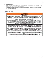
Page 11: ... HEATING AND FIRE PREVENT CONTACT WITH SAGGING OR LOOSE INSULATION OR FRAMING AND OTHER COMBUSTIBLE MATERIALS BLOCK OPENING INTO THE CHASE TO PREVENT ENTRY OF BLOWN IN INSULATION MAKE SURE INSULATION AND OTHER MATERIALS ARE SECURED WHEN CONSTRUCTING THE ENCLOSURE ALLOW FOR FINISHING MATERIAL THICKNESS TO MAINTAIN CLEARANCES FRAMING OR FINISHING MATERIAL CLOSER THAN THE MINIMUMS LISTED MUST BE CONS...

Page 12: ...12 W415 0379 E 04 24 12 It is best to frame your appliance after it is positioned Use 2x4 s and frame to local building codes 42 39 3 5 22 ...

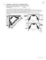
Page 13: ...sary to install a hearth extension with this appliance system When roughing in the appliance raise the appliance to accommodate for the thickness of the finished floor materials i e tile carpeting hard wood which if not planned for will interfere with the opening of the lower access door and the installation of many decorative flashing accessories Raise the appliance up to the height of the finish...

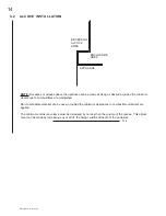
Page 14: ...he minimum clearances to combustibles are maintained Non combustible material can be used provided the minimum clearances to combustible materials are applied The minimum enclosure volume must be increased by no less than the volume of the recess This adjust ment can be made by increasing any or all of the height width and depth of the enclosure 71 2 ENCLOSURE AREA ...

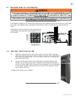
Page 15: ...C ARE CLEARLY MAINTAINED WHEN USING PAINT OR LACQUER TO FINISH THE MANTEL THE PAINT OR LACQUER MUST BE HEAT RESISTANT TO PREVENT DISCOLOURATION 73 1 MANTEL WIDTH 4 3 1 2 3 7 5 6 7 5 H E I G H T M A N T E L 4 4 NAILING TAB INSTALLATION 55 1A A Attach the nailing tabs to the corner posts using the 2 sheet metal screws sup plied Secure through the centre of the top and bottom slots in the nailing tab...

Page 16: ...rocess WARNING LOGS MUST BE PLACED IN THEIR EXACT LOCATION IN THE APPLIANCE DO NOT MODIFY THE PROPER LOG POSITIONS SINCE APPLIANCE MAY NOT FUNCTION PROPERLY DELAYED IGNITION AND CARBON SOOT DISTRIBUTION THROUGHOUT THE LIVING AREA MAY OCCUR THE LOGS ARE FRAGILE AND SHOULD BE HANDLED WITH CARE DO NOT PLACE CHARCOAL EMBERS VERMICULITE OR CHARCOAL LUMPS ON THIS BURNER ALL PREVIOUSLY APPLIED LOOSE MATE...

Page 17: ... the grate Place the top into the pocket provided on log 5 and allow to rest against the bracket of the log support REAR LOG SUPPORT LEFT TAB REAR TABS RIGHT TAB REAR TABS 1 A Prepare for log placement by ensuring the left rear and right tabs of the log support and firebox bottom are bent up to 90º to aid in locating the logs B Place the back log 1 onto the base of the fire box Ensure that the bac...

Page 18: ...ck the burner ports Blocked burner ports can cause an incorrect flame pattern Carbon deposits and delayed ignition PhazerTM logs glow when exposed to direct flame 5 3 GLOWING EMBERS 34 1 Place the lumps in front of the logs in a realistic manner taking care not to block any of the burner ports WARNING CHARCOAL EMBERS VERMICULITE AND CHARCOAL LUMPS ARE NOT TO BE PLACED ON THE BURNER WARNING APPLIAN...

Page 19: ...t the bottom left and right corners of the unit To remove the louvres pull the back tabs of the clips forward while pushing the louvre assembly back Lift the clip 5 8 L42 LOUVRE INSTALLATION 5 9 LOGO PLACEMENT Remove the backing of the logo supplied and place on the screen cover as indicated LOGO D The curtain mesh must be kept fully closed during operation to help prevent accidental burns from oc...

Page 20: ...t provided Ensure that the blower does not touch the appliance base or the firebox Attach the connectors from the black and white wires to the thermal switch and secure the thermal switch bracket to the bottom left of the unit using the screws provided Ensure that the thermal switch touches the firebox wall Attach the connectors from the black and red wires to the blower b l a c k white red VARIAB...

Page 21: ...turned on it will automatically start approximately 10 minutes after lighting the appliance and will run for approximately 30 45 minutes after the appliance has been turned off Use of the fan increases the output of heat Drywall dust will penetrate into the blower bearings causing irreparable damage Care must be taken to prevent drywall dust from coming into contact with the blower or its compartm...

Page 22: ...of the back log G Turn gas knob counter clockwise to pilot H Depress and hold gas knob while lighting the pilot with the push button ignitor Keep knob fully depressed for one minute then release If pilot does not continue to burn repeat steps 3 through 7 With pilot lit turn gas knob counter clockwise to on When the pilot has been turned off ignition of the main burner may be delayed from 1 2 minut...

Page 23: ...g Opening the air shutter will cause a more blue flame but can cause flame lifting from the burner ports The flame may not appear yellow immediately allow 15 to 30 minutes for the final flame colour to be established AIR SHUTTER ADJUSTMENT MUST ONLY BE DONE BY A QUALIFIED INSTALLER AIR SHUTTER OPENING VENTURI BURNER ORIFICE 49 1 AIR SHUTTER OPENINGS NG 3 16 LP 7 16 8 2 FLAME CHARACTERISTICS It s i...

Page 24: ...ust not be obstructed A In order to properly clean the burner and pilot assembly remove the logs rocks and or glass to expose both assemblies B Keep the control compartment media burner air shutter opening and the area surrounding the logs clean by vacuuming or brushing at least once a year C Check to see that all burner ports are burning Clean out any of the ports which may not be burning or are ...

Page 25: ...r Description of part Finish IDENTIFIES ITEMS WHICH ARE NOT ILLUSTRATED FOR FURTHER INFORMATION CONTACT YOUR AUTHORIZED DEALER 41 1 FAILURE TO POSITION THE PARTS IN ACCORDANCE WITH THIS MANUAL OR FAILURE TO USE ONLY PARTS SPECIFICALLY APPROVED WITH THIS APPLIANCE MAY RESULT IN PROPERTY DAMAGE OR PERSONAL INJURY WARNING 10 0 REPLACEMENTS 9 2 CARE OF PLATED PARTS 6 1 If the appliance is equipped wit...

Page 26: ...GDOI42BG 1 ORNAMENTAL INSET BRUSHED GOLD 31 GDOI42K 1 ORNAMENTAL INSET BLACK 31 GDOI42G 1 ORNAMENTAL INSET GOLD 15 12 22 24 30 14 13 7 23 29 19 18 21 20 2 4 17 16 COMPONENTS REF PART NO DESCRIPTION 13 W135 0151 SMALL LEFT LOG 2 14 W135 0152 SMALL RIGHT LOG 3 15 W135 0131 LEFT CROSSOVER LOG 4 16 W135 0132 CENTER LOG 5 17 W135 0133 RIGHT CROSSOVER LOG 6 18 W010 0864 PAN BURNER 19 W456 0038 38 NATURA...

Page 27: ...low Service or replace Oxygen Depletion Sensor System Correct piping and or regulator to provide correct pressure Ensure adequate supply pressure Pilot goes out when the gas knob is released The gas valve has an interlock device which will not allow the pilot burner to be lit until the thermocouple has cooled Allow approximately 60 seconds for the thermocouple to cool System is not correctly purge...

Page 28: ...n Depletion Sensor System Call the gas distributor Pilot goes out while standing Main burner is in OFF position Gas piping is undersized Turn on all gas appliances and see if pilot flame flutters diminishes or extinguishes especially when main burner ignites Monitor appliance supply working pressure Check if supply piping size is to code Correct all undersized piping Pilot flame is not large enoug...

Page 29: ... of the methods described in ANSI Z223 1 NFPA 54 or the applicable local code Not enough ventilation air Increase fresh air supply Use one of the methods described in ANSI Z223 1 NFPA 54 or the applicable local code Flame is impinging on the logs or combustion chamber Check that the logs are correctly positioned Open air shutter to increase the primary air See VENTURI ADJUSTMENT section Check the ...

Page 30: ...er plated trim or other components due to water weather damage long periods of dampness condensation damaging chemicals or cleaners will not be the responsibility of NAPOLEON All parts replaced under the President s Limited Lifetime Warranty Policy are subject to a single claim During the first 10 years NAPOLEON will replace or repair the defective parts covered by the lifetime warranty at our dis...

Page 31: ...31 W415 0379 E 04 24 12 13 0 SERVICE HISTORY 43 1 ...

Page 32: ...32 W415 0379 E 04 24 12 ...

Reviews: